Method and system for producing gas and liquid in a subterranean well

a technology of subterranean wells and gas and liquid, which is applied in the direction of fluid removal, earth-moving drilling, borehole/well accessories, etc., can solve the problems of gas loss and reduce the effective formation backpressure caused, so as to reduce the overall system back pressure, prevent vapor lock in the pump, and improve the pump efficiency

Inactive Publication Date: 2007-04-24
MARATHON OIL CO
View PDF10 Cites 14 Cited by
  • Summary
  • Abstract
  • Description
  • Claims
  • Application Information

AI Technical Summary

Benefits of technology

[0010]The system prevents vapor lock in the pump, eliminates the need for a gas shroud on the pump, and improves the efficiency of the pump. The system also prevents liquid from surfacing and collecting in liquid production equipment, and reduces overall system back pressures caused by liquid low spots in the liquid production equipment. In addition, the system improves gas flow in the annulus, reduces gas loss through production with the liquid, and reduces effective formation backpressures caused by a higher density fluid in the annulus above the producing formation.

Problems solved by technology

In addition, the system improves gas flow in the annulus, reduces gas loss through production with the liquid, and reduces effective formation backpressures caused by a higher density fluid in the annulus above the producing formation.

Method used


Image

  • Method and system for producing gas and liquid in a subterranean well
  • Method and system for producing gas and liquid in a subterranean well
  • Method and system for producing gas and liquid in a subterranean well

Examples


example 1

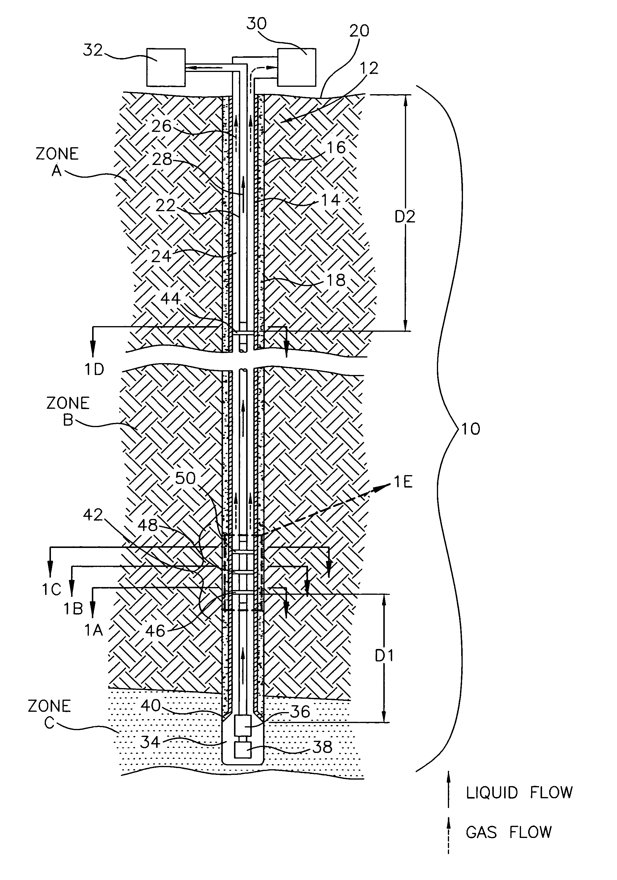
[0058]FIG. 2B is a graph illustrating operational parameters of a methane gas well with the system 10 (FIG. 2A) located in the Powder River Basin of Wyoming. In the system 10 (FIG. 2A), the set of baffle plates 42 was installed approximately fifteen feet above the casing shoe 40, the pump 36 and the cavity 34. The single baffle plate 44 was installed approximately thirty to sixty feet from the surface 20.

[0059]In FIG. 2B“Daily Gas MCFPD” is represented by the line with diamond points, “Daily Water BWPD” is represented by the line with square points, and “Average Fluid Over Pump” is represented by the line with triangular points. Also in FIG. 2B, the horizontal axis quantifies time in one month increments, and the vertical axis quantifies the parameter.

[0060]As indicated by FIG. 2B, system 10 with the set of baffle plates 42 and the single baffle plate 44 was installed between “Month 12” and “Month 13”. Following installation of the system 10, “Daily Gas MCFPD” increased relative to ...

example 2

[0061]FIG. 3B and FIG. 3C are graphs illustrating operational parameters of a methane gas well with the system 10A (FIG. 3A) located in the Powder River Basin of Wyoming. In the system 10A (FIG. 3A), the single baffle plate 44 was installed approximately sixty feet from the surface 20.

[0062]In FIG. 3B“Daily Gas MCFPD” is represented by the line with diamond points, “Daily Water BWPD” is represented by the line with square points, and “Average Fluid Over Pump” is represented by the line with triangular points. Also in FIG. 3B, the horizontal axis quantifies the time in one month increments, and the vertical axis quantifies the parameter.

[0063]As indicated by FIG. 3B, the system 10A (FIG. 3A) with the single baffle plate 44 was installed in the well between “Month 13” and “Month 14”. Following installation of the system 10A (FIG. 3A), “Daily Gas MCFPD” increased relative to the preceding three months, “Average Fluid Over Pump” decreased relative to the preceding eight months, and “Dai...

example 3

[0066]FIG. 4B and FIG. 4C are graphs illustrating operational parameters of a methane gas well with the system 10B (FIG. 4A) installed therein located in the Powder River Basin of Wyoming. In this example, the set of baffle plates 42 was installed approximately fifteen feet above the casing shoe 40, the pump 36 and the cavity 34.

[0067]In FIG. 4B“Daily Gas MCFPD” is represented by the line with diamond points, “Daily Water BWPD” is represented by the line with square points, and “Average Fluid Over Pump” is represented by the line with triangular points. Also in FIG. 4B, the horizontal axis quantifies time in one month increments, and the vertical axis quantifies the parameter.

[0068]As indicated by FIG. 4B, the system 10B with the set of baffle plates 42 was installed in the well between “Month 12” and “Month 13”. Following installation of the system 10B, “Daily Gas MCFPD” increased relative to the preceding months, “Average Fluid Over Pump” decreased relative to the preceding months...


PUM


Abstract

A method for producing a gas and a liquid in a subterranean well includes the step directing a gas flow in a well annulus through one or more baffle plates to separate at least some of the liquid from the gas. The method can also include the steps of directing the separated liquid down the annulus towards a producing formation of the well, dehydrating the gas flow proximate to a surface of the well, and then directing the dehydrated gas flow to the surface. A system for performing the method includes a set of baffle plates located proximate to the producing formation configured to provide a tortuous path for the gas flow through the annulus, and a single baffle plate located proximate to the surface configured to dehydrate the gas flow. In addition to separating the liquid from the gas flow, the set of baffle plates maintains a single phase wet gas above the baffle plates, and a liquid phase below the baffle plates.

Description

FIELD OF THE INVENTION[0001]This invention relates generally to subterranean wells, and more particularly to a method and system for producing gas and liquid in a subterranean well.BACKGROUND OF THE INVENTION[0002]Subterranean wells are used to produce various gases and liquids. For example, a subterranean well can be used to produce methane gas and liquid water from a coal seam. This type of subterranean well can include a well bore from the surface to the coal seam, a well casing cemented to the well bore, and a metal tubular within the well casing. The well can also include a submerged pump located within an under reamed cavity in the coal seam. During production from the well, water is pumped from the cavity, and through the tubular, to water production equipment at the surface. In addition, gas flows from the coal seam into the cavity, and through the annulus between the tubular and the well casing, to gas production equipment at the surface.[0003]The methane gas can cause vari...

Claims


Application Information

Patent Timeline
Patent Type & Authority Patents(United States)
IPC IPC(8): E21B43/38E21B21/06
CPCE21B43/38E21B43/385
Inventor SMITH, THOMAS B.PRESTON, YALE M.
Owner MARATHON OIL CO
Why Eureka
Try Eureka