No-return loop fuel system

a fuel system and loop technology, applied in the direction of machine/engine, engine diaphragm, diaphragm valve, etc., can solve the problems of fuel rail pressure control range, overpressure condition, pressure spike, etc., to prevent fuel vapor lock at the fuel rail, reduce engine emissions, and improve engine start-up

Inactive Publication Date: 2005-02-17
TI GRP AUTOMOTIVE SYST LLC
View PDF18 Cites 38 Cited by
  • Summary
  • Abstract
  • Description
  • Claims
  • Application Information

AI Technical Summary

Benefits of technology

[0015] Objects, features and advantages of this invention are to provide a no-return loop fuel system which utilizes a reverse flowing valve assembly to control fuel pressure delivered to the injectors during various engine operating conditions and preserve fuel pressure within the system at a minimal value during engine shut down. The system avoids supplying exce

Problems solved by technology

Yet another scenario of an overpressure condition may be caused by a slow response time of the variable speed pump.
This could cause a pressure spike if the variable speed fuel pump can not immediately respond thus the pressure relief check valve will open to relieve fuel pressure at the rail.
Unfortunately, because the pressure relief check valve is referenced to tank pressure as opposed to pump output pressure, the relief set pressure of the “T” configuration utilizing a variable speed fuel pump must be set well above system operating pressure.
As a result, the range of pressure control within the fuel rail is limited and the fuel injectors exposed to higher fuel pressure are more likely to leak when the engine is shut-down.
A second disadvantage of the typical “T” configuration is that a separate bypass line and associated fittings are required thus increasing the manufacturing costs and assembly required.
The previously described “T” configuration also has a disadvantage o

Method used


Image

  • No-return loop fuel system
  • No-return loop fuel system
  • No-return loop fuel system

Examples


Embodiment Construction

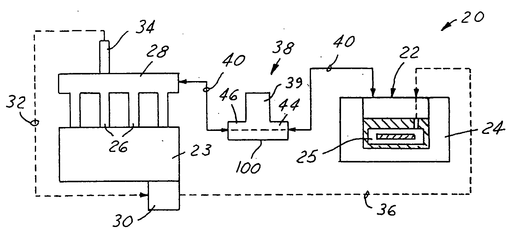
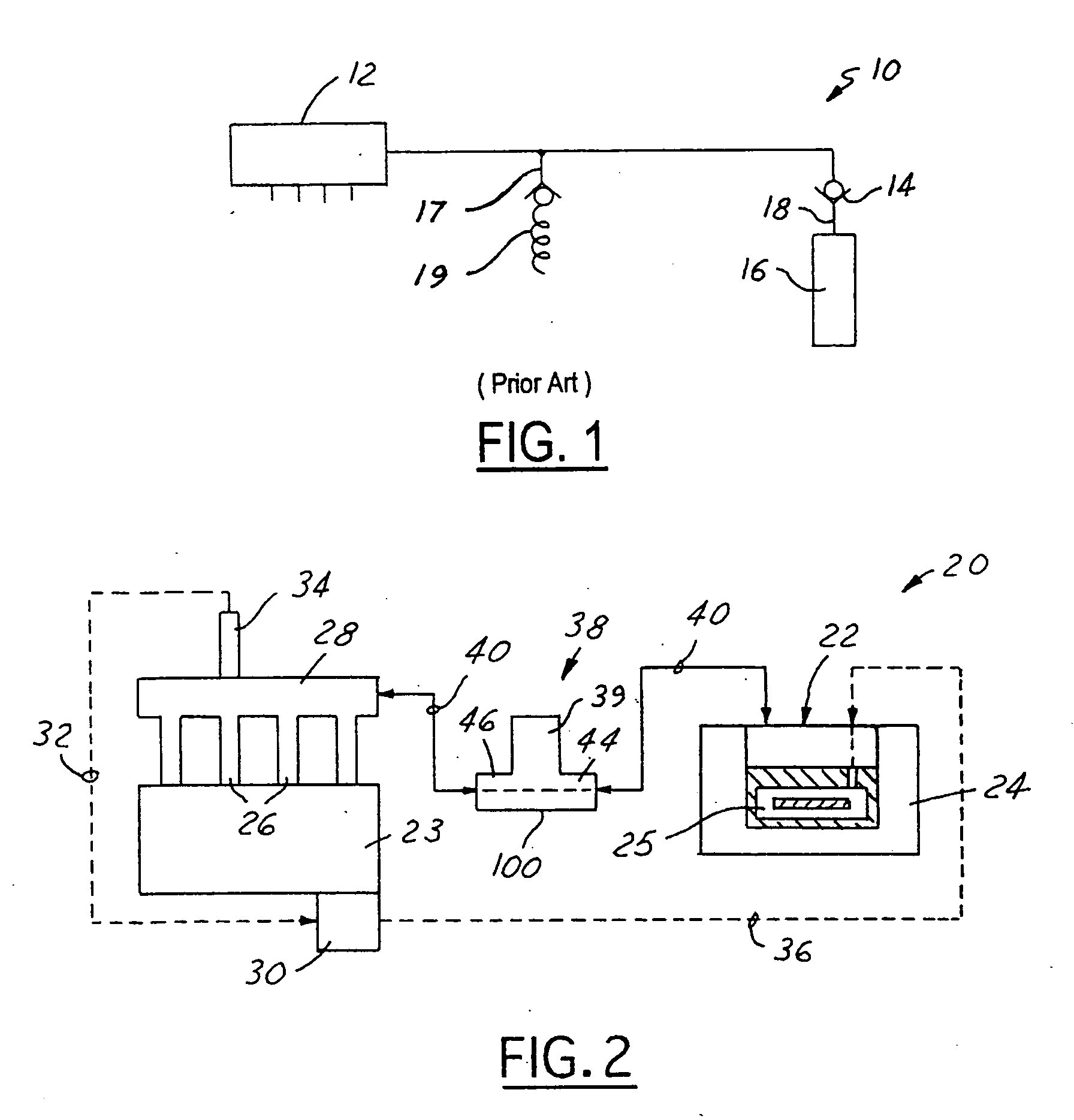
[0031] As best illustrated in FIG. 2 a no-return loop fuel system 20 of the present invention has a variable speed turbine fuel pump 22 preferably disposed within a fuel tank 24 which delivers fuel to a series of injectors 26 to operatively deliver fuel from a common manifold tube or fuel rail 28 to respective combustion chambers of an engine 23. The speed of the fuel pump 22 is controlled via a computer or a controller 30 (preferably part of the vehicle engine central processing unit) which receives an input signal 32 from a pressure transducer 34 mounted on the fuel rail 28 which then processes the signal and outputs a speed control signal 36 to the pump 22. Preferably, the pressure at the fuel rail 28 varies depending upon engine speed or consumption demand and any other of a variety of engine parameters processed by the controller 30.

[0032] A pressure valve assembly 38 has a pressure relief, regulator, or control valve 39 interposed in a fuel line 40 communicating between the f...


PUM


Abstract

A no-return loop fuel injection system supplies fuel from a fuel pump to an injector fuel rail, through a fuel line. A biased closed pressure control valve communicates with the fuel line and has a valve head preferably of a diaphragm type carrying a fuel side having first and second areas which are segregated and defined by a valve seat when the pressure control valve is closed. An opposite second side of the pressure control valve is exposed to a reference pressure and a closure biasing force. The pressure control valve opens when a hydraulic opening force induced by a fuel pressure exerted upon the first area, plus a fuel pressure exerted upon the second area, is greater than the net reference pressure and closure biasing forces. Preferably, the first area is smaller than the second area, thus manipulating the effects of the fuel pressures exerted upon the first and second areas with respect to opening the valve. When the pressure control valve is open, the system operating pressure exposed to both the first and second areas is sufficient to produce the hydraulic force necessary to keep the valve open. Preferably, the pressure control valve is part of a pressure valve assembly of a fuel pump module located inside a fuel tank. The pressure valve assembly preferably has a flow check valve orientated in a parallel flow configuration to the pressure control valve when the fuel pump is of a variable speed type, or, for systems utilizing constant speed pumps the check valve is replaced with a flow bypass orifice.

Description

REFERENCE TO RELATED APPLICATION [0001] Applicant claims the benefit of each of CIP application Ser. No. 10 / 766,393, filed Jan. 28, 2004; which claims the benefit of parent non-provisional application Ser. No. 10 / 443,159, filed May 22, 2003 and published Dec. 25, 2003; which claims the benefit of provisional application Ser. No. 60 / 390,377, filed Jun. 21, 2002.FIELD OF THE INVENTION [0002] This invention relates to automotive engine fuel systems and more particularly to a no-return loop fuel system having a variable speed fuel pump and a pressure valve assembly. BACKGROUND OF THE INVENTION [0003] There are two general types of no-return loop or returnless fuel injection systems for a combustion engine. The first type, referred to as a “T” configuration, is used in fuel system applications where the fuel pressure within an injector fuel rail is held constant regardless of the mass fuel amount flowing through the injectors. The second type is referred to as a “parallel” configuration ...

Claims


Application Information

Patent Timeline
IPC IPC(8): F02M33/08F02M69/00F02M37/00F02M69/46F02M69/54F16K7/14F16K31/126F16K35/00
CPCF02D33/006F02M33/08F02M37/0023F02M37/0029F16K35/00F02M63/028F02M69/465F02M69/54F16K7/14F02M37/0058
Inventor CRARY, LYNWOOD F.FORGUE, JOHN R.JOHANSEN, MARK R.
Owner TI GRP AUTOMOTIVE SYST LLC
Why Eureka
Try Eureka