Inkjet head

a technology of inkjet and head, which is applied in the field of inkjet head, can solve the problems of difficult to vary the amount of heat corresponding to ink temperature, difficulty in properly jetting high viscosity ink, and inability to properly jet high viscosity ink, etc., and achieves the effect of easy embedding and more effective in heating ink equally

Active Publication Date: 2007-04-24
KONICA MINOLTA INC
View PDF6 Cites 12 Cited by
  • Summary
  • Abstract
  • Description
  • Claims
  • Application Information

AI Technical Summary

Benefits of technology

[0020]In view of the aforementioned problems, it is therefore an object of the invention to provide an inkjet head that is capable of jetting uniform ink droplets by making uniform the temperature of the ink in the inkjet head, which further enables the ink viscosity to be uniform.
[0021]It is another object of the invention to provide an inkjet head which can transfer heat efficiently by integrally molding an ink heater with a manifold without using any adhesives and any high thermal conductivity materials, and eliminate the possibility to increase the manufacturing man-hour and cost, and can heat the ink equally with a simple configuration.

Problems solved by technology

But due to the fact that UV curable ink has a higher viscosity than general ink, it is difficult to jet highly viscous ink properly.
However, in the above mentioned ink heater which is disposed in an ink tank, the ink may change in temperature before being jetted from an ink jetting opening, and therefore the ink may be not well jetted.
In the case of the ink heater for heating the filter case of an inkjet head as described in JP-Tokukaihei-10-790A, it is difficult to vary the amount of heat corresponding to ink temperatures, and this makes it troublesome to maintain the ink at a predetermined temperature.
Therefore a poor ink jetting may be caused.
However, the ink in the manifold has an area where the temperature tends to be difficult to decrease and an area where the temperature tends to be easy to decrease because the heat dissipating condition in the inkjet head varies from place to place.
As a result, a variation in ink viscosity occurs, and therefore the ink droplets may be jetted unequally and a poor image formation may be caused.
In this technique, while silicon resin has a relatively good thermal conductivity, it has difficulty in transferring heat equally from the heater to the ink because the thermal resistance of the adhesives is large, and therefore the heat transfer efficiency is poor.
In addition, unlike a plane film type heater, a rod-shaped heater cannot heat the ink equally, because it has a small heat generation surface.
No concrete manner to embed the heater therein, however, is disclosed.
After all, it is difficult to extend a thin plane heater to be even so as to embed it in a surface because it curls up.

Method used


Image

  • Inkjet head
  • Inkjet head
  • Inkjet head

Examples


first embodiment

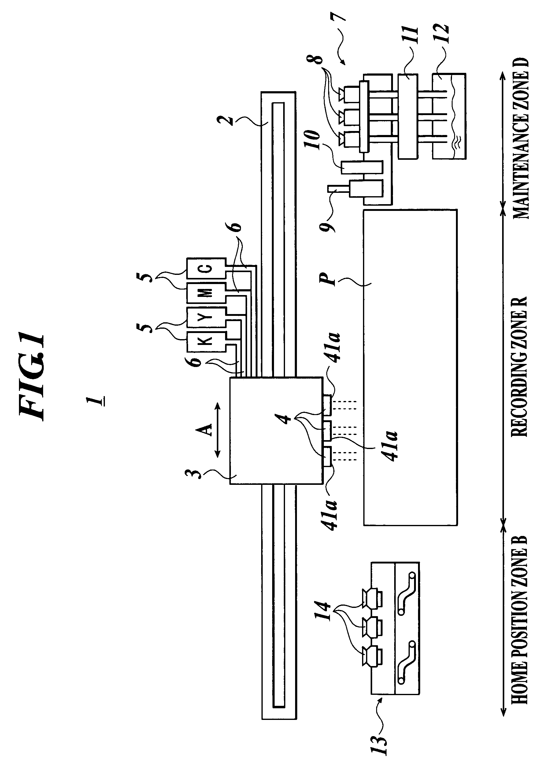
[0089]With reference to FIG. 1, the entire configuration of the inkjet printer in accordance with the first embodiment of the invention will be explained as follows. FIG. 1 illustrates the entire configuration of the inkjet printer in accordance with the first embodiment of the invention.

[0090]An inkjet printer 1 is an apparatus that records images on a recording medium P whereto ink is jetted. The inkjet printer 1 is equipped with a certain conveying expedient which is not shown in the figure, and which conveys the recording medium P in a secondary scanning direction that is perpendicular to a main scanning direction A while passing through a recording zone R.

[0091]A carriage rail 2 that extends along the horizontal scanning direction A is positioned on the upper side of recording zone R. A freely movable carriage 3, steered by the carriage rail 2, is disposed on the carriage rail 2.

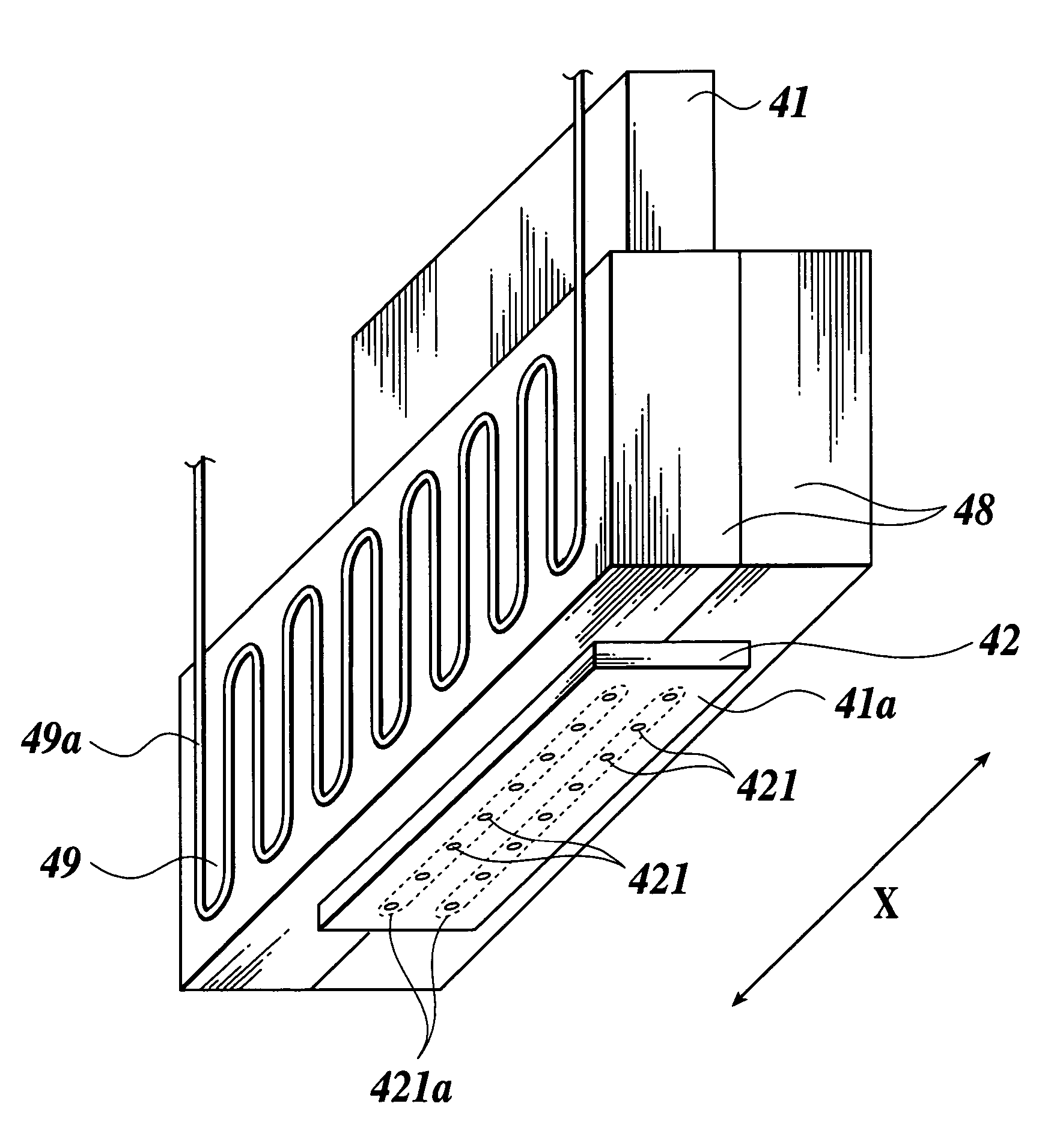
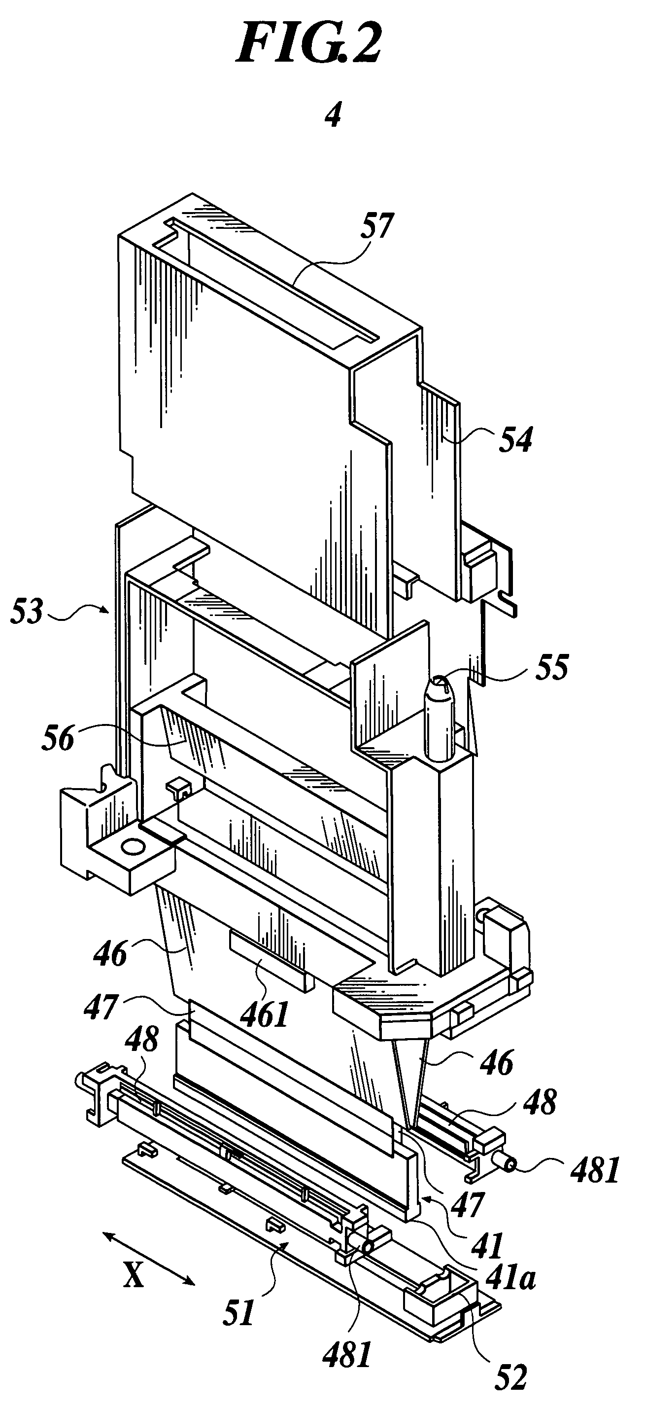
[0092]The carriage 3 which is loaded with an inkjet head 4 for jetting ink onto recording medium P, ...

second embodiment

[0139]The inkjet head in accordance with the second embodiment of the invention will be explained in the following.

[0140]FIG. 9 is a cross sectional view of the inkjet head in accordance with the second embodiment of the invention. FIG. 10 is an exploded perspective view of FIG. 9. FIG. 11 is a fragmentary sectional view taken in the direction of arrows substantially along the line (iii)—(iii) of FIG. 9.

[0141]Referring to FIG. 9 and FIG. 10, the inkjet printer head chip 110 (hereafter referred as head chip), which is used as an actuator, consists mainly of piezoelectric ceramics wherein a plurality of channels (part or the entire ink flow passage within the head chip) 112a, 112b having ink jetting openings (nozzle) 111a and 111b for printing are lined up. A first manifold 120a and a second manifold 120b are respectively fixed to the lateral sides (upper side and low side in FIG. 9) of the head chip 110.

[0142]The head chip 110 is a ceramics component which is formed after a piezoelec...


PUM


Abstract

An inkjet head having: an inkjet head chip having ink jetting openings which are lined up to form a nozzle row on a front surface of the inkjet head chip; a manifold attached securely to a side of the inkjet head chip and leading ink to the inkjet head chip; and an ink heater which is in thermal contact through the manifold with ink in the manifold and which varies in heat generation density in a direction of the nozzle row.

Description

BACKGROUND OF THE INVENTION[0001]1. Field of the Invention[0002]The invention relates to an inkjet head which attains desirable images by jetting ink onto a recording medium, and more particularly, to an inkjet head for heating and jetting high viscosity ink.[0003]2. Description of Related Art[0004]An inkjet printer which jets ink onto a recording medium, e.g. a paper, a thin plastic plate or the like, to record a predetermined image has been proposed, and is now in practical use. The inkjet printer, which is equipped with an inkjet head having ink jetting openings, records a predetermined image on a recording medium by jetting ink onto the recording medium while the inkjet head is moved along a predetermined direction.[0005]The inkjet printer jets ink through an inkjet head that utilizes a piezoelectric element. The inkjet head includes an inkjet head chip having ink jetting openings which are lined up to form a nozzle row on a front surface of the inkjet head chip, and a manifold ...

Claims


Application Information

Patent Timeline
Patent Type & Authority Patents(United States)
IPC IPC(8): B41J29/38B41J2/04B41J2/05
CPCB41J29/38
Inventor KOMATSU, KATSUAKIMAKITA, MASAHIRO
Owner KONICA MINOLTA INC
Why Eureka
Try Eureka