Turbine bucket with optimized cooling circuit

a cooling circuit and bucket technology, applied in the direction of engine fuction, machine/engine, reaction engine, etc., can solve the problems of limited local creep in the trailing edge of the bucket design, large capacity limitation of such an engine, and difficulty in maximizing cooling ability, so as to maximize the useful life at base load operation, minimize negative effects on performance, and maximize cooling ability

Active Publication Date: 2007-04-24
GENERAL ELECTRIC CO
View PDF30 Cites 18 Cited by
  • Summary
  • Abstract
  • Description
  • Claims
  • Application Information

AI Technical Summary

Benefits of technology

[0007]In an exemplary embodiment of the invention, a turbine bucket includes a cooling circuit through a dovetail section, a shank section, and an airfoil section. The cooling circuit is configured to maximize cooling ability and maximize useful life at base load operation at firing temperatures of up to 2084° F. while minimizing negative effects on performance.

Problems solved by technology

The capacity of such an engine is limited to a large extent by the ability of the material from which the turbine blades (sometimes referred to herein as “buckets”) are made to withstand thermal stresses which develop at such relatively high operating temperatures.
The problem may be particularly severe in an industrial gas turbine engine because of the relatively large size of the turbine blades.
The resulting seven-hole bucket was to be in uprated machines firing at 2075° F. Due to unbalanced stack issues, the seven-hole bucket design was severely local creep limited in its trailing edge.
A redesigned baseline six-hole bucket was better balanced and also incorporated turbulation; however, in an attempt to recover some performance, the cooling flow through the component was drastically reduced, leading to bulk creep life limitations.

Method used


Image

  • Turbine bucket with optimized cooling circuit
  • Turbine bucket with optimized cooling circuit
  • Turbine bucket with optimized cooling circuit

Examples


Embodiment Construction

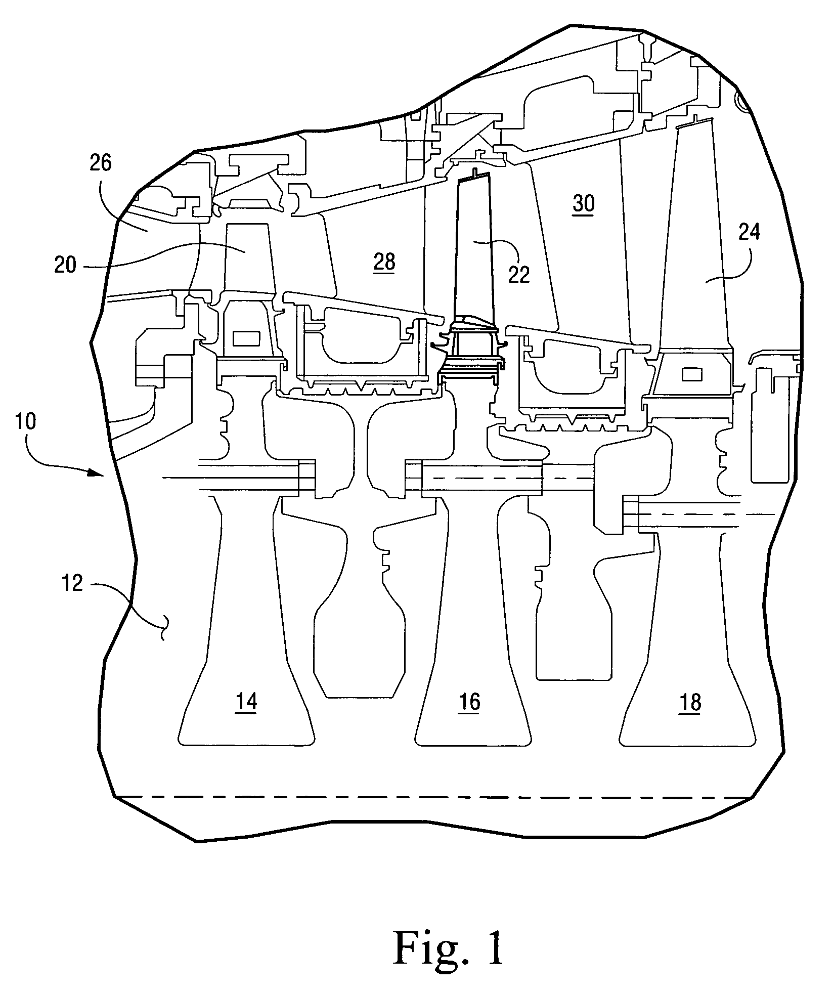
[0016]With reference to FIG. 1, a portion of a turbine is generally designated at 10. The turbine 10 includes a rotor 12 having first, second and third stage rotor wheels 14, 16 and 18 having buckets 20, 22 and 24 in conjunction with the respective stator vanes 26, 28 and 30 of the various rotor stages. It will be appreciated that a three stage turbine is illustrated.

[0017]The second stage includes the rotor wheel 16 on which buckets 22 are mounted in axial opposition to the upstream stator vanes 28. It will be appreciated that a plurality of the buckets 22 are spaced circumferentially one from the other about the second stage wheel 16, and in this instance, there are 92 buckets mounted on the second stage wheel 16.

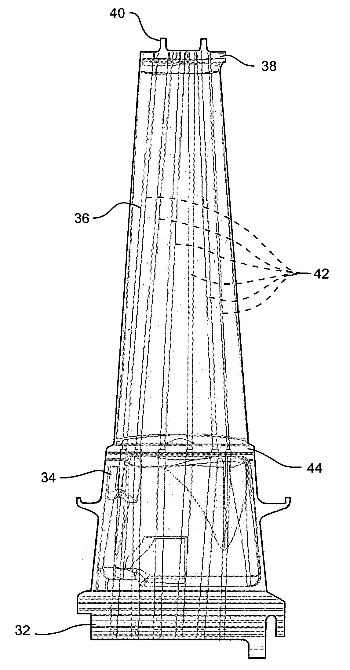
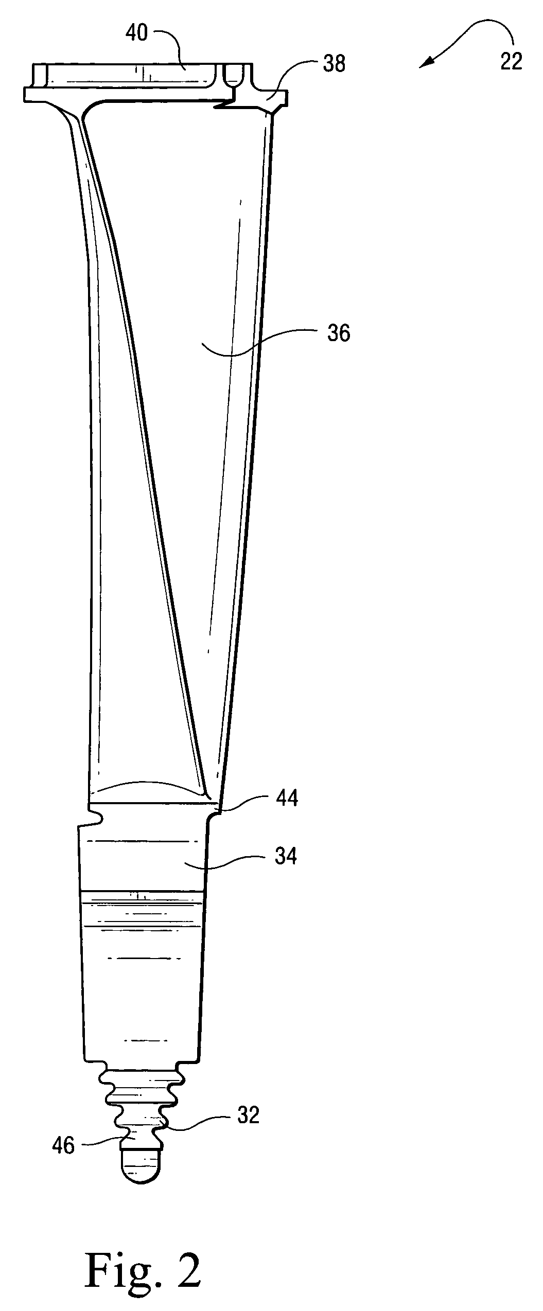
[0018]With reference to FIGS. 2–4, the turbine bucket 22 includes a dovetail section 32, a shank section 34, and an airfoil section 36. A tip 38 of the airfoil section 36 includes seal rails 40.

[0019]In an effort to overcome bulk creep life limitations, it is desirable to...


PUM


Abstract

A turbine bucket includes a cooling circuit through a dovetail section, a shank section and an airfoil section. The cooling circuit is configured to maximize cooling ability and maximize a useful life at base load operation at firing temperatures of up to 2084° F. while minimizing negative effects on performance. The cooling circuit includes a plurality of cooling holes having predetermined positions and sizes, resulting in increased cooling flow near a trailing edge of the airfoil section and effecting turbulation in the airfoil section to increase bulk and local creep margins throughout the airfoil section.

Description

BACKGROUND OF THE INVENTION[0001]The present invention relates generally to turbine buckets and, more particularly, to a turbine bucket incorporating an optimized cooling circuit with modified cooling hole sizes and positions in an effort to maximize cooling ability and ensure a longer useful life.[0002]In gas turbine engines and the like, a turbine operated by burning gases drives a compressor which furnishes air to a combustor. Such turbine engines operate at relatively high temperatures. The capacity of such an engine is limited to a large extent by the ability of the material from which the turbine blades (sometimes referred to herein as “buckets”) are made to withstand thermal stresses which develop at such relatively high operating temperatures. The problem may be particularly severe in an industrial gas turbine engine because of the relatively large size of the turbine blades.[0003]To enable higher operating temperatures and increased engine efficiency without risking blade f...

Claims


Application Information

Patent Timeline
Patent Type & Authority Patents(United States)
IPC IPC(8): F01D5/18F03B3/12
CPCF01D5/187F05D2260/221
Inventor MURIITHI, KAHWAI GACHAGO
Owner GENERAL ELECTRIC CO
Why Eureka
Try Eureka