Gutter foam filter

a filter and gutter technology, applied in the field of gutter foam filter, can solve the problems of gutter and downspout system overflow, leaf catchment and embedded in perforations, paper scraps, etc., and achieve the effect of convenient cutting

Active Publication Date: 2007-04-24
TJM INNOVATIONS
View PDF15 Cites 31 Cited by
  • Summary
  • Abstract
  • Description
  • Claims
  • Application Information

AI Technical Summary

Benefits of technology

[0015]The gutter foam filter elements of the present invention are generally triangular lengths of plastic foam material placed in and extending the length of a conventional “K” type gutter located at the base of the roof of a dwelling or other building. The foam material is preferably supplied in four-foot sections and the required number of sections of foam are stuffed within the gutter so as to extend its full length. The foam filter elements may be inserted below gutter spikes where those are used in the mounting of the gutter to the wall of the building. The foam material is an open pore foam such as porous polyether foam of about 10–20 cells per square inch. The foam is flexible and easily cut to fit a desired length. The gutter foam filter allows rainwater to travel through the filter while excluding leaves which blow away when dry.
[0016]The foam is generally in the form of a right triangle in cross section and so disposed in the gutter as to have a rear side of the right triangle extending along the back of the gutter and an upper side of the triangle spanning the open space between the upper lip of the front wall and the rear upper wall forming the open portion of the gutter. The angular side forming the hypotenuse of the triangle extends from the lower rear wall to the upper front wall, leaving a void in the lower front portion of the gutter for rainwater to flow to a downspout. The lower corner of the foam element is preferably truncated so as to partially extend outward, parallel to the upper side, from the gutter back wall and along its bottom wall to provide added stability to the foam element as located in the gutter structure.
[0017]The present invention provides improved elements and arrangements thereof for the purposes described and which is inexpensive, dependable and fully effective in accomplishing its intended purposes.

Problems solved by technology

Rain gutters, commonly installed along the lower edges of a sloping roof under the eaves to catch water draining from the roof, frequently become clogged with leaves, paper scraps and the like, carried to the roof by wind or gravity and washed into the gutter.
This debris fills and clogs the gutters, causing water to overflow, and plugs downspouts, producing overflow of the gutter and downspout system.
Leaves often become caught and embedded in the perforations and openings of such, structures, however, and must be removed by hand to prevent clogging.
Also, such systems add substantial expense to the gutter and downspout system.
Known rigid foam systems either require a special gutter shape, provide inadequate drainage, or are of a complex shape making them expensive to make and install.
They may be subject to clogging with pollen or dust.

Method used


Image

  • Gutter foam filter
  • Gutter foam filter
  • Gutter foam filter

Examples


Embodiment Construction

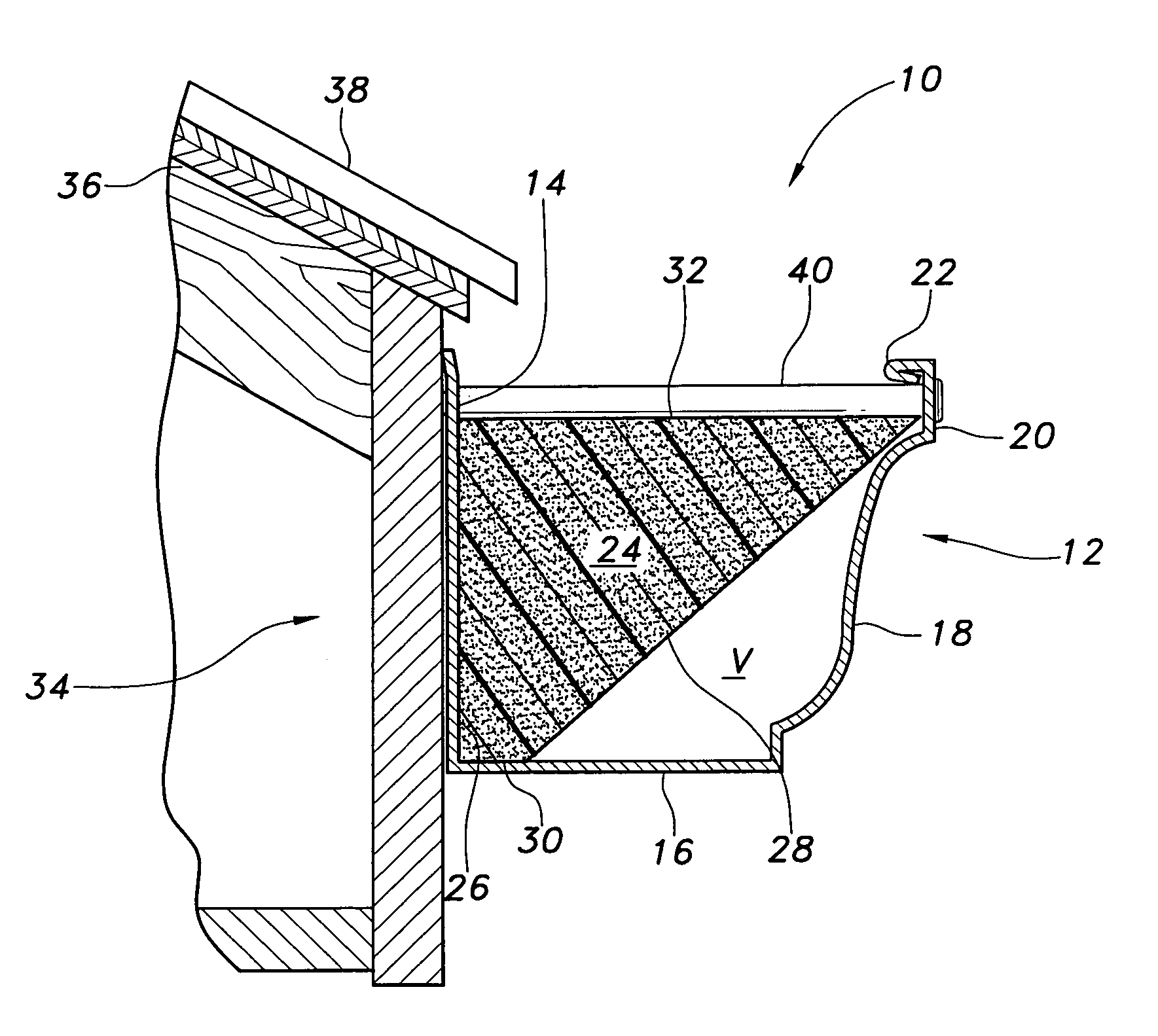
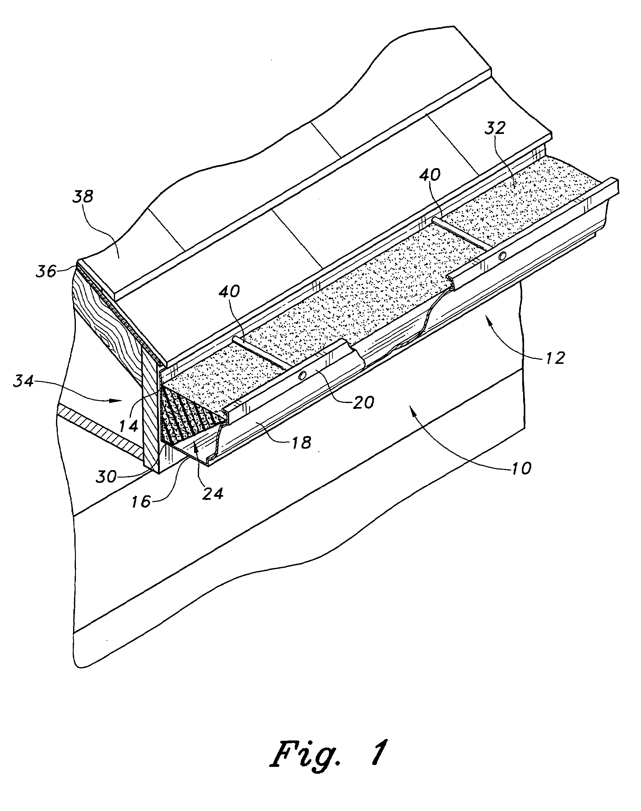
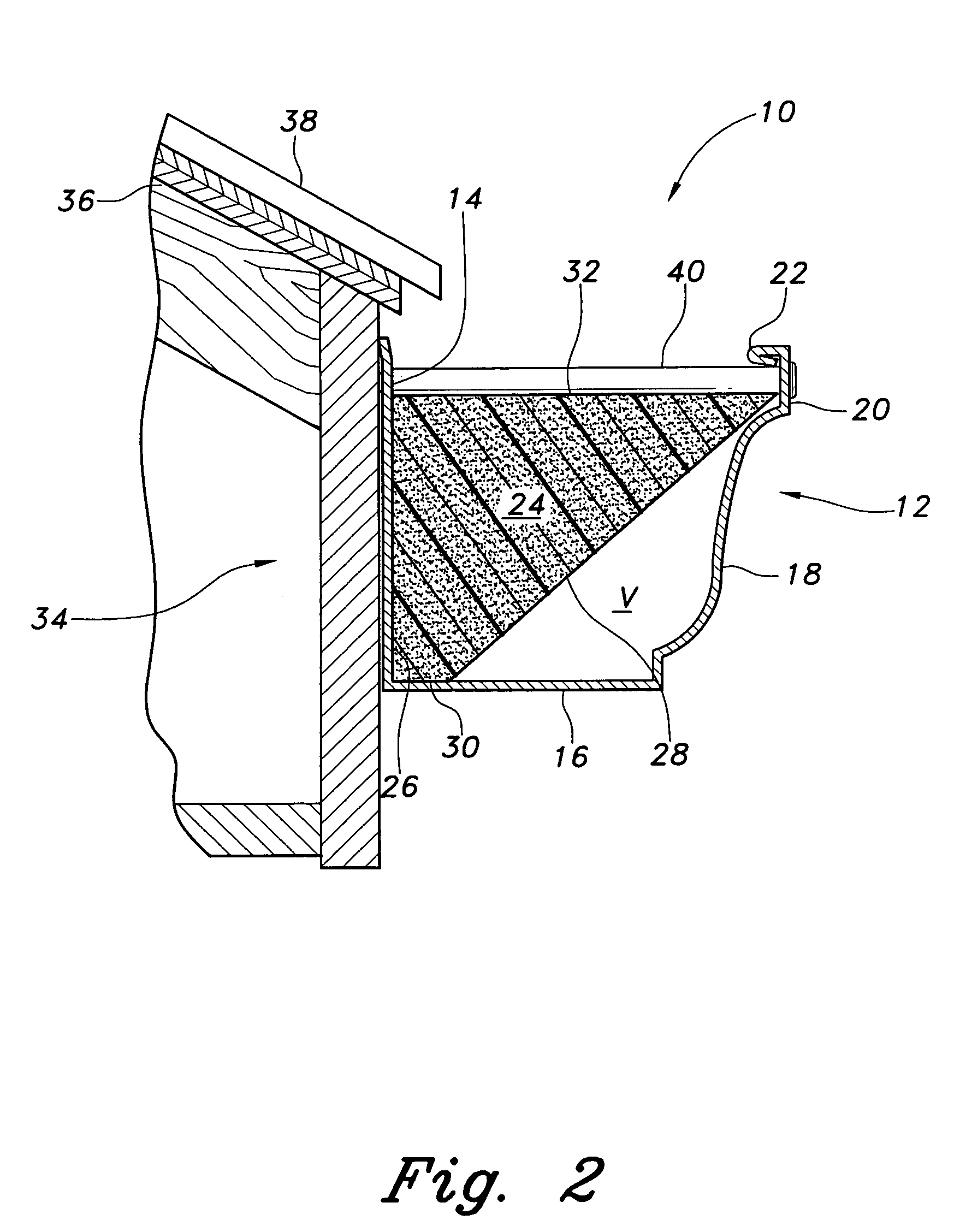
[0023]The gutter foam filter elements of the present invention are generally triangular lengths of plastic foam material placed in and extending the length of a conventional “K” type gutter located at the base of the roof of a dwelling or other building. The foam material is preferably supplied in four-foot sections and the required number of sections of foam are stuffed within the gutter so as to extend its full length.

[0024]Referring to the Figures, the inventive gutter system is generally referred to by element number 10. Gutter system 10 includes gutter 12 which is connected at corners and leads to downspouts in a conventional manner. Gutter 12 has a back wall 14, a bottom wall 16, and a front wall 18. Gutter front wall 18 has an upper lip 20 having an inward and downward pointing inner lip portion 22. The space between the upper lip 20 and the back wall 14 is open to receive rainwater runoff from roof 36. The inventive foam filter insert 24 has the general cross section of a ri...


PUM

PropertyMeasurementUnit
lengthaaaaaaaaaa
flexibleaaaaaaaaaa
lengthaaaaaaaaaa

Abstract

The gutter foam filter elements are generally triangular, four-foot lengths of flexible plastic open-cell foam material placed in and extending the full length of a conventional “K” type or similar roof gutter. The foam filter elements may be inserted within the gutter below gutter spikes. The foam material is an open-pore polyether foam of 10–20 cells per square inch which allows rainwater to travel through the filter while excluding leaves. The foam is generally in the form of a right triangle and so disposed in the gutter as to have one side extending along the back of the gutter and the other side of the triangle spanning the open space across the upper open portion of the gutter. The sloped wall defines a void in the lower front portion of the gutter for rainwater flow to a downspout. The lower corner of the element is truncated forming a lower support wall.

Description

BACKGROUND OF THE INVENTION[0001]1. Field of the Invention[0002]The present invention relates to rain gutters for houses or the like. More particularly, the present invention relates to rain gutters having structure to prevent blocking of the gutters by foreign materials.[0003]2. Description of the Related Art[0004]Rain gutters, commonly installed along the lower edges of a sloping roof under the eaves to catch water draining from the roof, frequently become clogged with leaves, paper scraps and the like, carried to the roof by wind or gravity and washed into the gutter. This debris fills and clogs the gutters, causing water to overflow, and plugs downspouts, producing overflow of the gutter and downspout system.[0005]Many devices have been proposed to overcome this problem, such as perforated plates and screens, designed to collect and divert leaves and debris before they are carried into the gutters and the downspout system. Leaves often become caught and embedded in the perforati...

Claims


Application Information

Patent Timeline
Patent Type & Authority Patents(United States)
IPC IPC(8): B01D35/02E04D13/076
CPCE04D13/076
Inventor JONES, ROBERT W.
Owner TJM INNOVATIONS
Why Eureka
Try Eureka