Data cable for mechanically dynamic environments

a data cable and dynamic environment technology, applied in the direction of power cables, cables, insulated conductors, etc., can solve the problems of affecting the stability of the cable, and the cable may be exposed to rough handling, etc., to achieve the effect of facilitating stability

Active Publication Date: 2007-04-24
BELDEN TECHNOLOGY INC
View PDF158 Cites 49 Cited by
  • Summary
  • Abstract
  • Description
  • Claims
  • Application Information

AI Technical Summary

Benefits of technology

[0013]According to various aspects and embodiments of the invention, there is provided a twisted pair cable that may be particularly suitable for use in mechanically dynamic environments. Such a cable may have one of various lay configurations that facilitate stability under force and stresses such as bending, cornering, rigorous movement, rough handling, etc., that may arise in industrial environments and / or during installations using various automatic cable dispensing devices, as discussed below.

Problems solved by technology

For example, cables may be exposed to rough handling during installation of a structured cabling architecture for a local area network (LAN), during cable pulling and tying, etc.
One example of relatively harsh treatment of cables occurs in automatic cable dispensing devices.
However, the automatic features of such devices often apply forces and various mechanical stresses to the cable during operation.
Such relatively harsh treatment may alter the configuration and / or arrangement of the twisted pairs making up the cable.
Reflected electrical energy may have various adverse effects on data transmission, including reduced output power, signal distortion and dispersion, signal loss (e.g., attenuation), etc.
For example, high frequency signals tend to be more sensitive to distortion effects associated with return loss.
Accordingly, higher performance cables may be more vulnerable to return loss effects caused by rough handling of the cables.
For example, an impedance mismatch between a cable and a load that is coupled to the cable may cause reflections that adversely affect return loss.
Other reflections may stem from unintended variation in cable properties, non-uniformities and / or discontinuities along the length of a cable.
Mechanical stresses on conventional cables in mechanically dynamic environments may result in variation in the intended lay configuration of the cable which may degrade the cable's return loss characteristics such that the cable no longer meets the performance requirements of its intended category.
However, various factors, such as rough handling and / or a tendency of the insulated conductors to untwist may cause some separation between the two conductors at various points along the length of the twisted pair.
This variation in the center-to-center distance may cause the impedance of the twisted pair to vary along the length of the twisted pair 50, resulting in undesirable signal reflections that affect return loss.
As a result, the dielectric composition of the twisted pair may vary along the longitudinal length of the twisted pair, causing further variation characteristic impedance of the twisted pair that may, in turn, produce unwanted signal reflections that degrade the return loss of the cable.

Method used


Image

  • Data cable for mechanically dynamic environments
  • Data cable for mechanically dynamic environments
  • Data cable for mechanically dynamic environments

Examples


Embodiment Construction

[0024]Various conventional high performance cables may not be usable in mechanically dynamic environments or industrial settings due to their susceptibility to variation in the cable's configuration when introduced to various forces and mechanical stresses. Moreover, conventional cables may be vulnerable to performance degradation during installation, rough handling and / or other relatively harsh treatment.

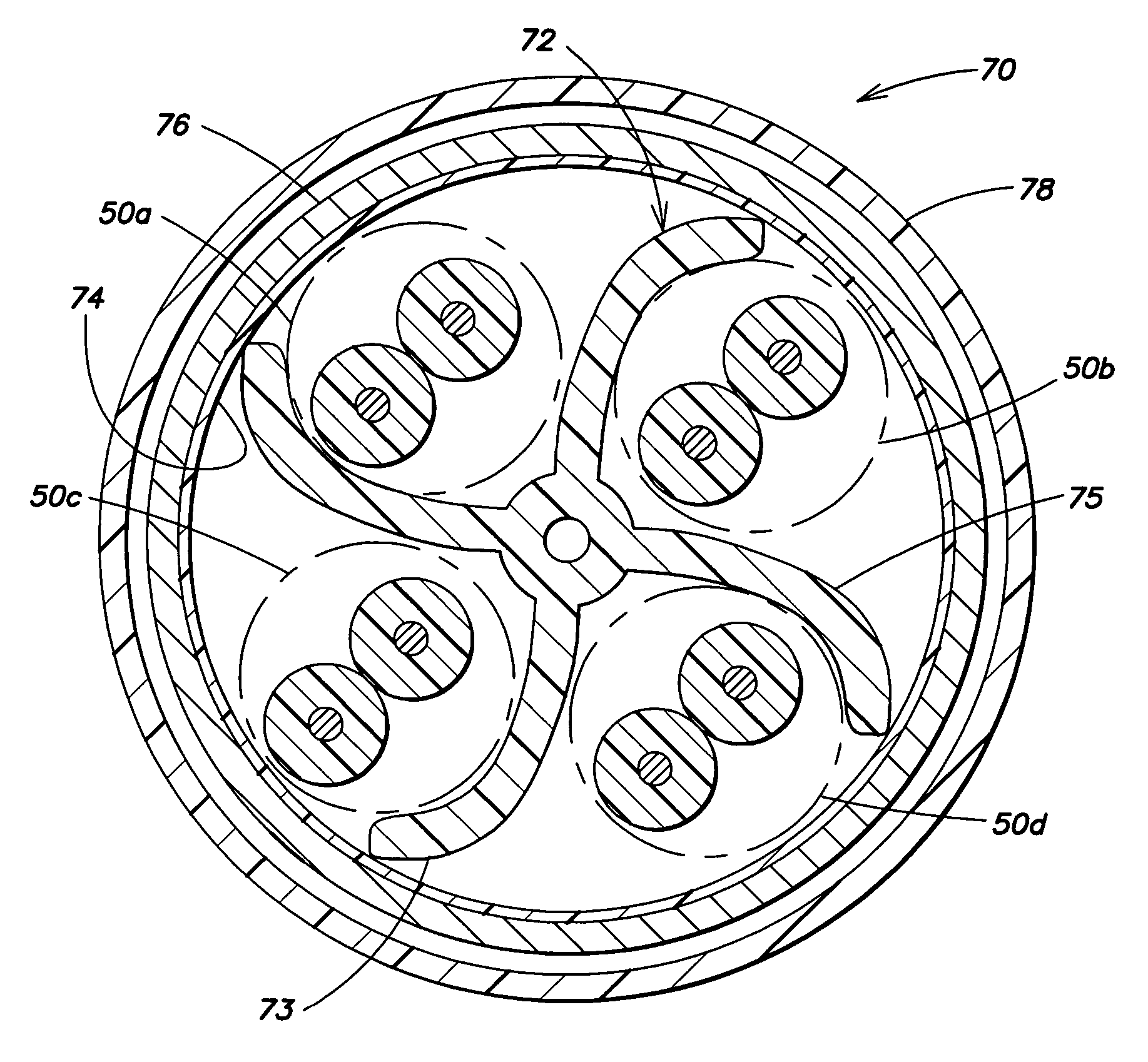
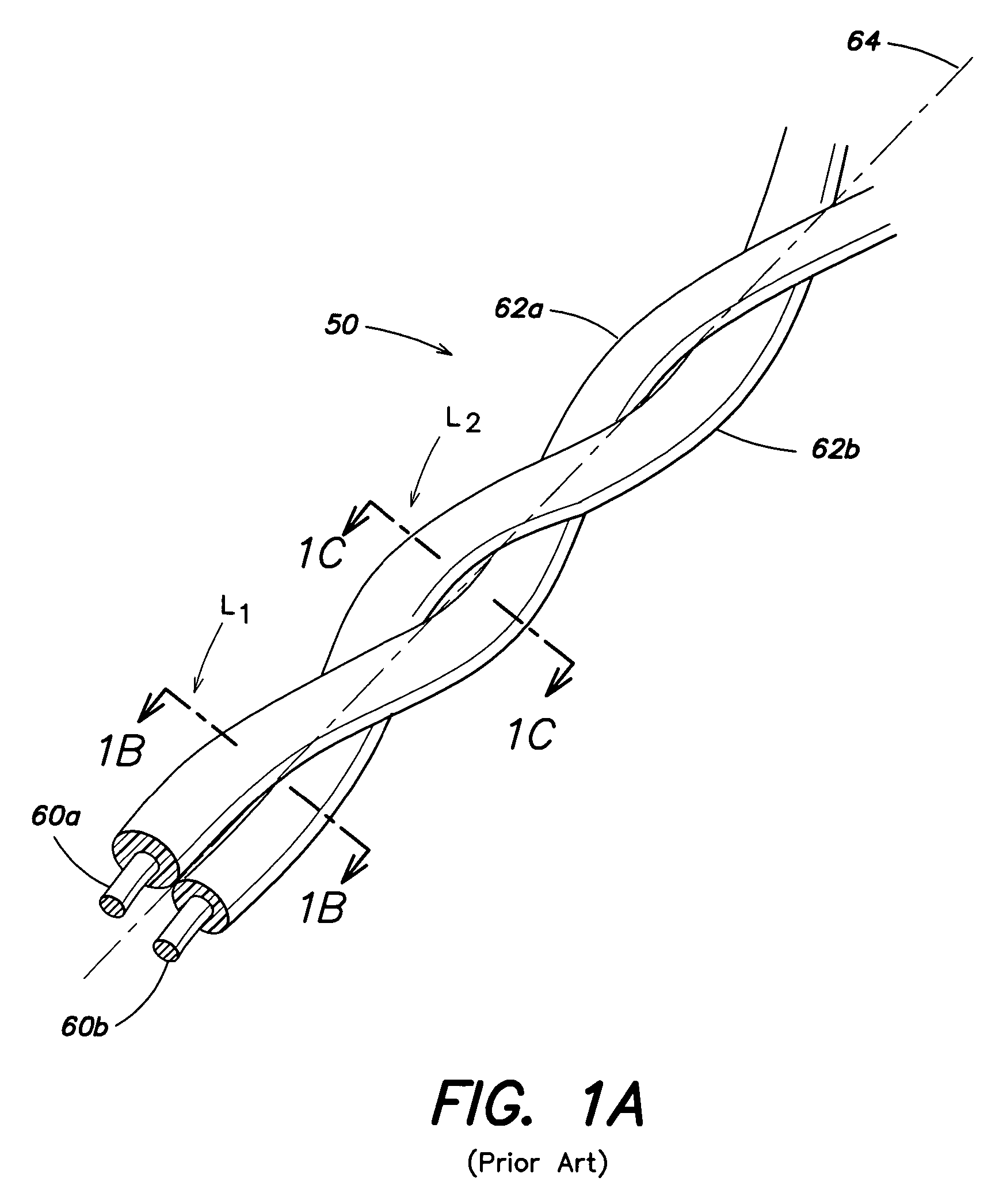
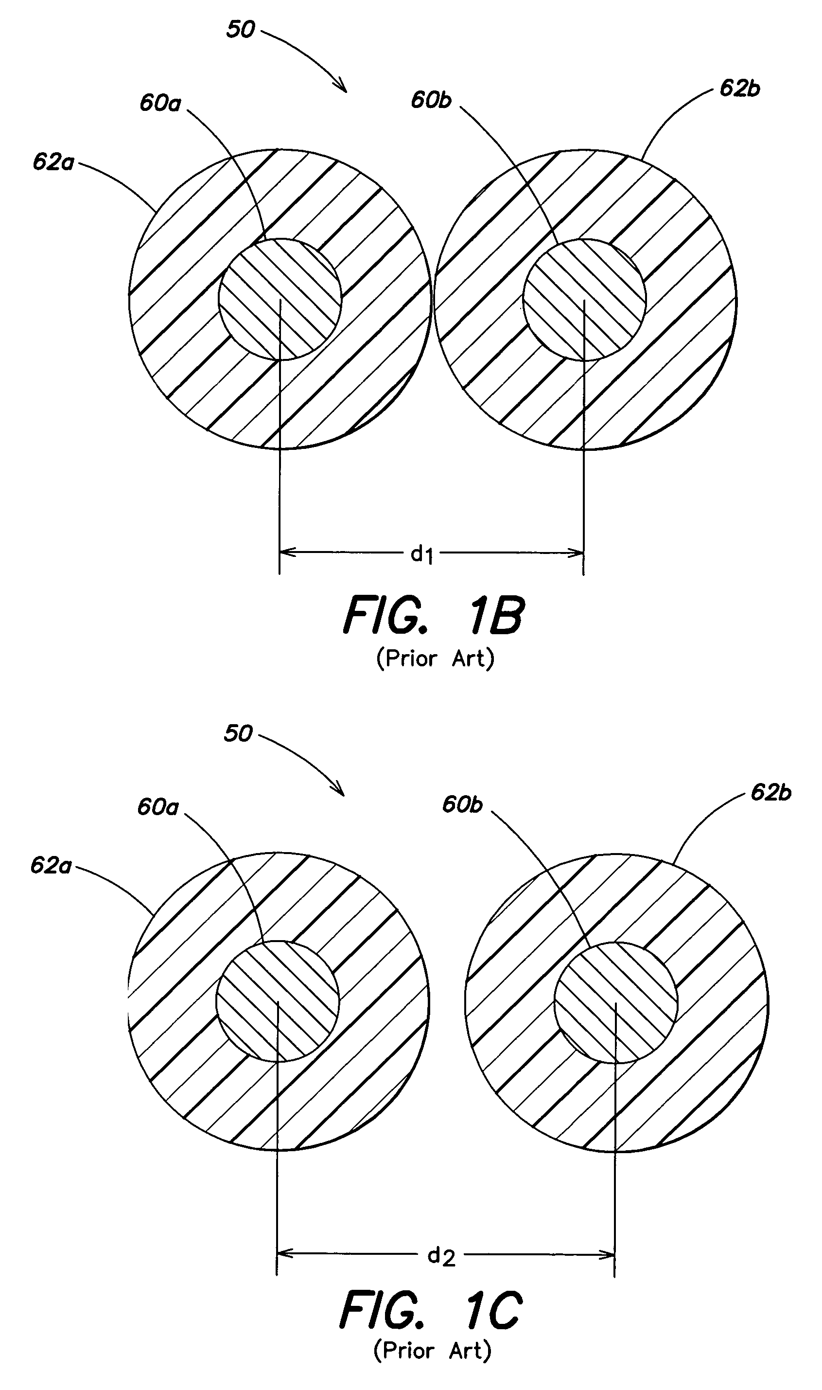
[0025]Accordingly, Applicant has recognized and appreciated various lay configurations that facilitate stability under force and stresses such as bending, cornering, rigorous movement, rough handling, etc., that may arise in industrial environments and / or during installations using various automatic cable dispensing devices, etc. The term “lay configuration” as used herein refers to the arrangement of various components of a data communications cable. In particular, lay configuration refers to the various relationships within a cable, such as the relationships between conductors in...


PUM

PropertyMeasurementUnit
lengthaaaaaaaaaa
lengthaaaaaaaaaa
lengthaaaaaaaaaa

Abstract

A multi-pair cable including a plurality of twisted pairs of insulated conductors, each having a closing lay length (twist lay length measured after the twisted pairs are cabled together with a particular cable lay) of less than about 0.6 inches. The plurality of twisted pairs are twisted together with a cable lay of greater than about three inches to form the cable. In some examples, the multi-pair cable may further comprise a separator disposed between the first and second twisted pairs. In another example, a ratio between a longest closing lay length and a shortest closing lay length in the cable is less than 1.65 inches. In another example, the cable further includes at least one additional twisted pair of conductors having a closing lay length that is greater than about 0.6 inches, and the cable lay length is less than about four inches.

Description

BACKGROUND[0001]1. Field of the Invention[0002]The present invention relates to high-speed data communications cables comprising at least two twisted pairs of insulated conductors. More particularly, the invention relates to high-speed data communications cables that may be exposed to force, stress, rough handing and / or other disturbances present in mechanically dynamic environments.[0003]2. Discussion of the Related Art[0004]High-speed data communications cables often include pairs of insulated conductors twisted together generally in a double-helix pattern about a longitudinal axis. Such an arrangement of insulated conductors, referred to herein as “twisted pairs,” facilitates forming a balanced transmission line for data communications. One or more twisted pairs may subsequently be bundled and / or bound together to form a data communications cable.[0005]A cable may undergo various mechanical stresses during handling and use. For example, cables may be exposed to rough handling dur...

Claims


Application Information

Patent Timeline
Patent Type & Authority Patents(United States)
IPC IPC(8): H01B3/44
CPCH01B11/04H01B7/18
Inventor CLARK, WILLIAM T.
Owner BELDEN TECHNOLOGY INC
Why Eureka
Try Eureka