System and method for locating and positioning an ultrasonic signal generator for testing purposes

a technology of ultrasonic signal generator and positioning system, which is applied in the direction of analysing solids using sonic/ultrasonic/infrasonic waves, instruments, and reradiation, etc., can solve the problems of transducer couple to the material, large and complex shape, and difficulty in accommodating non-flat or evenly mildly contoured composite materials

Inactive Publication Date: 2007-04-24
LOCKHEED MARTIN CORP
View PDF40 Cites 7 Cited by
  • Summary
  • Abstract
  • Description
  • Claims
  • Application Information

AI Technical Summary

Problems solved by technology

Particularly for aircraft application, those composite material components, which may be large and complex in shape, are often flight critical necessitating strict assurance of material and structural integrity.
Unfortunately, these materials are sometimes fabricated with imperfections or develop them after several hours of use.
This inhomogeneity in the structure severely weakens it, providing a situation which might result in catastrophic failure.
The disadvantages of the conventional methods are many, including difficulty in accommodating non-flat or evenly mildly contoured composite materials.
Another disadvantage is the requirement that the transducer couple to the material via a water path.
To accommodate highly contoured and complex shaped components using conventional techniques often requires extremely time-intensive test set up preparation.
For those ultrasonic testing systems which use high power gas lasers such as CO2 lasers, the large and bulky size of the laser complicates the integration of the ultrasonic testing system with the GPS as the end segment of the mechanical armature must be capable of supporting a significantly heavy weight at its end.
The large size and bulky weight of the light source itself often demands the use of a very large GPS capable of supporting the heavy weight of an ultrasonic testing system as it is maneuvered around the test object to perform data acquisition from a variety of perspectives.
Many typical laser testing systems are hampered when the ultrasonic energy generator is not positioned properly relative to the part to be tested.
When this happens, the test results may need to be corrected, or in the case of testing relative strengths of different parts, this test may be completely inconclusive.
Further, when the ultrasonic signal is generated, the resulting ultrasonic signal affects certain areas and / or volumes of the tested object.
In this case, many systems that rely on manual positioning err on a conservative side.
This results in hugely overcompensated testing of the part since the overlaps are huge.

Method used


Image

  • System and method for locating and positioning an ultrasonic signal generator for testing purposes
  • System and method for locating and positioning an ultrasonic signal generator for testing purposes
  • System and method for locating and positioning an ultrasonic signal generator for testing purposes

Examples


Embodiment Construction

[0029]Preferred embodiments of the present invention are illustrated in the FIGURES, like numerals being used to refer to like and corresponding parts of the various drawings.

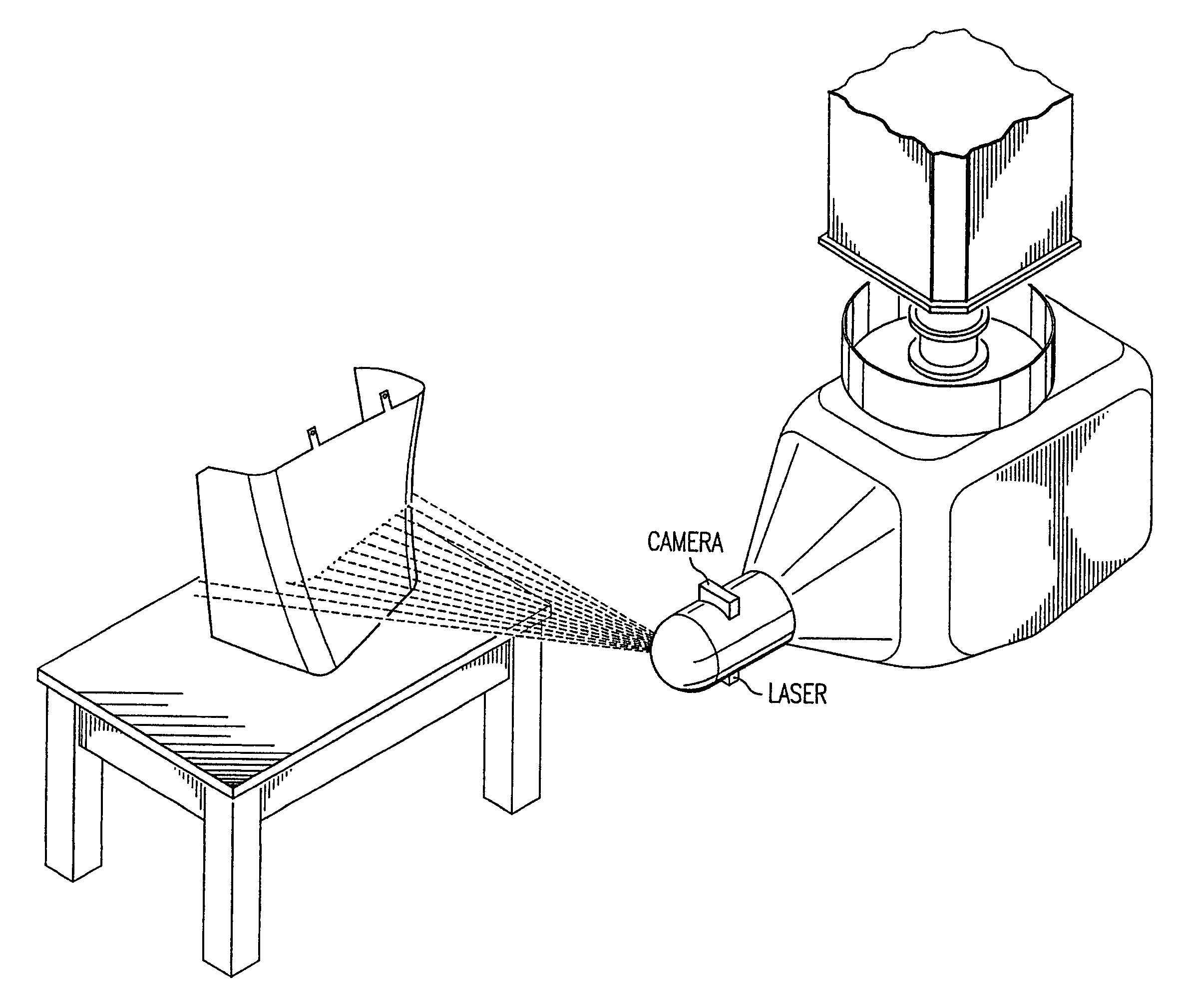
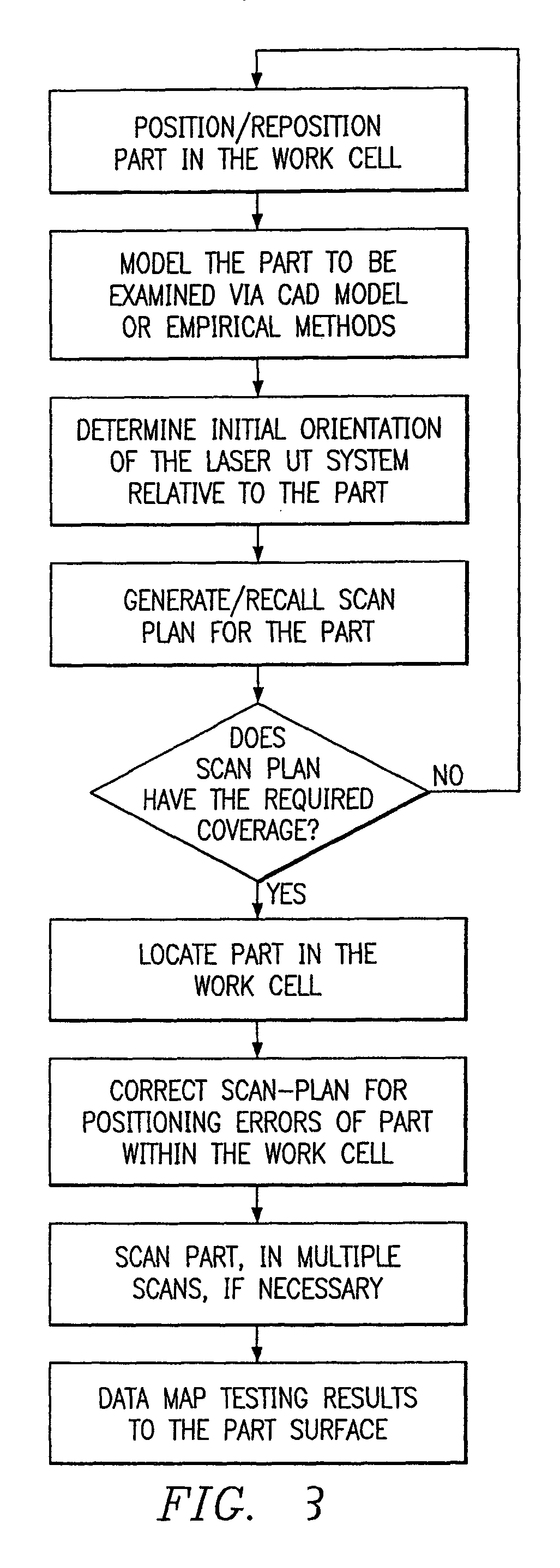
[0030]The present invention employs a gantry positioning system with an integral laser beam delivery system for delivering a laser beam delivered by a remote laser source to a test object for performing ultrasonic testing to detect any material defects in the test object. The gantry positioning system provides for scanning the entire test object from various fields of view to map out the test object using laser ultrasonic techniques. Data are recorded from all of the fields of view and later processed to provide for not only the detection of any such material defects, but also their location within the test object.

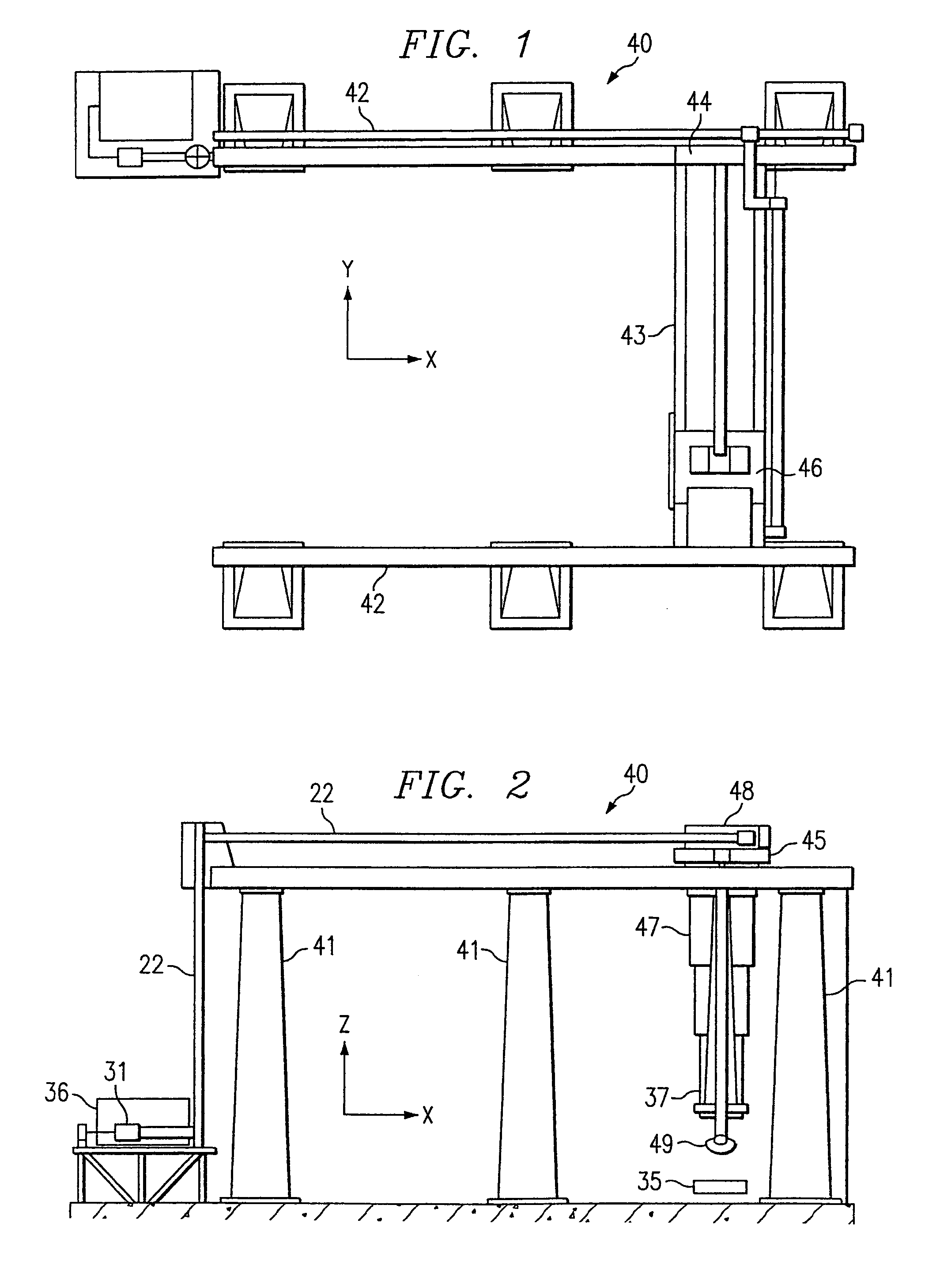
[0031]FIG. 1 shows one embodiment 30 of a gantry positioning and ultrasonic testing system with an integral laser beam delivery system. A laser beam 11 is generated by a remote laser source 31 and ins...


PUM

PropertyMeasurementUnit
angle of incidenceaaaaaaaaaa
ultrasonic testingaaaaaaaaaa
ultrasonic energiesaaaaaaaaaa

Abstract

The invention is directed to an ultrasonic testing system. The system tests a manufactured part for various physical attributes, including specific flaws, defects, or composition of materials. The part can be housed in a gantry system that holds the part stable. An energy generator illuminates the part within energy and the part emanates energy from that illumination. Based on the emanations from the part, the system can determined precisely where the part is in free space. The energy illumination device and the receptor have a predetermined relationship in free space. This means the location of the illumination mechanism and the reception mechanism is known. Additionally, the coordinates of the actual testing device also have a predetermined relationship to the illumination device, the reception device, or both. Thus, when one fixes the points in free space where the part is relative to either of the illumination device or the reception device, one can fix the point and / or orientation of the testing device to that part as well. It should be noted that the results of the point and / or orientation detection may also be used in an actuator and control system. If the position of the testing device needs to be altered with respect to the tested object, the control system and actuator may use the results of this determination to move the testing device relative to the tested object.

Description

RELATED APPLICATIONS[0001]This application claims priority of and is a continuation of U.S. patent application Ser. No. 09 / 907,493, filed Jul. 16, 2001 now U.S. Pat No. 6,643,002 entitled “SYSTEM AND METHOD FOR LOCATING AND POSITIONING AN ULTRASONIC SIGNAL GENERATOR FOR TESTING PURPOSES,”, and is incorporated herein by reference in its entirety.[0002]This application claims priority of U.S. Provisional Application Ser. No. 60 / 218,340, filed Jul. 14, 2000 entitled “Remote Laser Beam Delivery System and Method for Use with a Robotic Positioning System for Ultrasonic Testing Purposes,”, and is incorporated herein by reference in its entirety.[0003]Additionally, this application is related to and incorporates by reference U.S. patent application Ser. No. 09 / 416,399 filed on Oct. 10, 1999 entitled “METHOD AND APPARATUS FOR DETECTING ULTRASONIC SURFACE DISPLACEMENTS USING POST-COLLECTION OPTICAL AMPLIFICATION” to Thomas E. Drake.TECHNICAL FIELD OF THE INVENTION [0004]The present invention...

Claims


Application Information

Patent Timeline
Patent Type & Authority Patents(United States)
IPC IPC(8): G01B11/24G01S19/48G01B11/03G01B17/00G01N29/04G01N29/24G01S3/78G01S5/02G01S5/16G01S13/89G01S15/89G01S17/46G01S17/89
CPCG01N29/04G01N29/2418G01S5/0247G01S5/16G01S13/89G01S15/8906G01S17/46G01S17/89G01N2291/0231G01N2291/2694
Inventor DRAKE, JR., THOMAS E.
Owner LOCKHEED MARTIN CORP
Why Eureka
Try Eureka