Emergency-stop device

a servomotor and emergency stop technology, applied in the direction of circuit-breaking switches, dynamo-electric converter control, program control, etc., can solve the problems of two input circuits going out of order successively, insufficient to enhance the reliability of switches and relays, and inability to detect failure for a long time. , to achieve the effect of enhancing reliability

Active Publication Date: 2007-04-24
FANUC LTD
View PDF9 Cites 13 Cited by
  • Summary
  • Abstract
  • Description
  • Claims
  • Application Information

AI Technical Summary

Benefits of technology

[0009]The present invention provides an emergency-stop device capable of promptly detecting failure of emergency-stop signal circuits without stopping power supply to a servomotor provided in a robot system or a machine tool etc. to enhance reliability.
[0020]From the present invention, the following beneficial effects which cannot be obtained by the conventional technique can be expected.
[0022](2) By periodical monitoring, leaving failure undetected can be prevented and failure of an emergency-stop signal circuit can be detected with certainty.

Problems solved by technology

However, it is not enough to enhance the reliability of switches and relays, since the input circuit through which the emergency stop signal is supplied to the CPU uses semiconductor devices and the safety thereof is not ensured.
However, in the case of a controller requiring long continuous operation, supply of an emergency stop input is rare and detection of failure cannot be carried out for a long time.
In the case of a controller like this, even if it is dualized, there is a risk that the two input circuits go out of order successively, before failure is detected.
However, stopping the controller every time checking is performed is not desirable, since it lowers the working efficiency.

Method used


Image

  • Emergency-stop device
  • Emergency-stop device
  • Emergency-stop device

Examples


Embodiment Construction

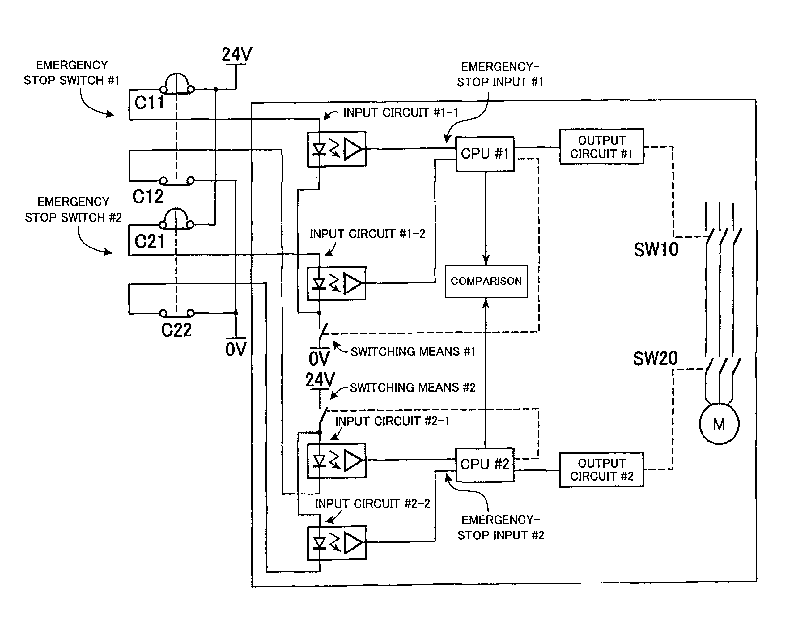
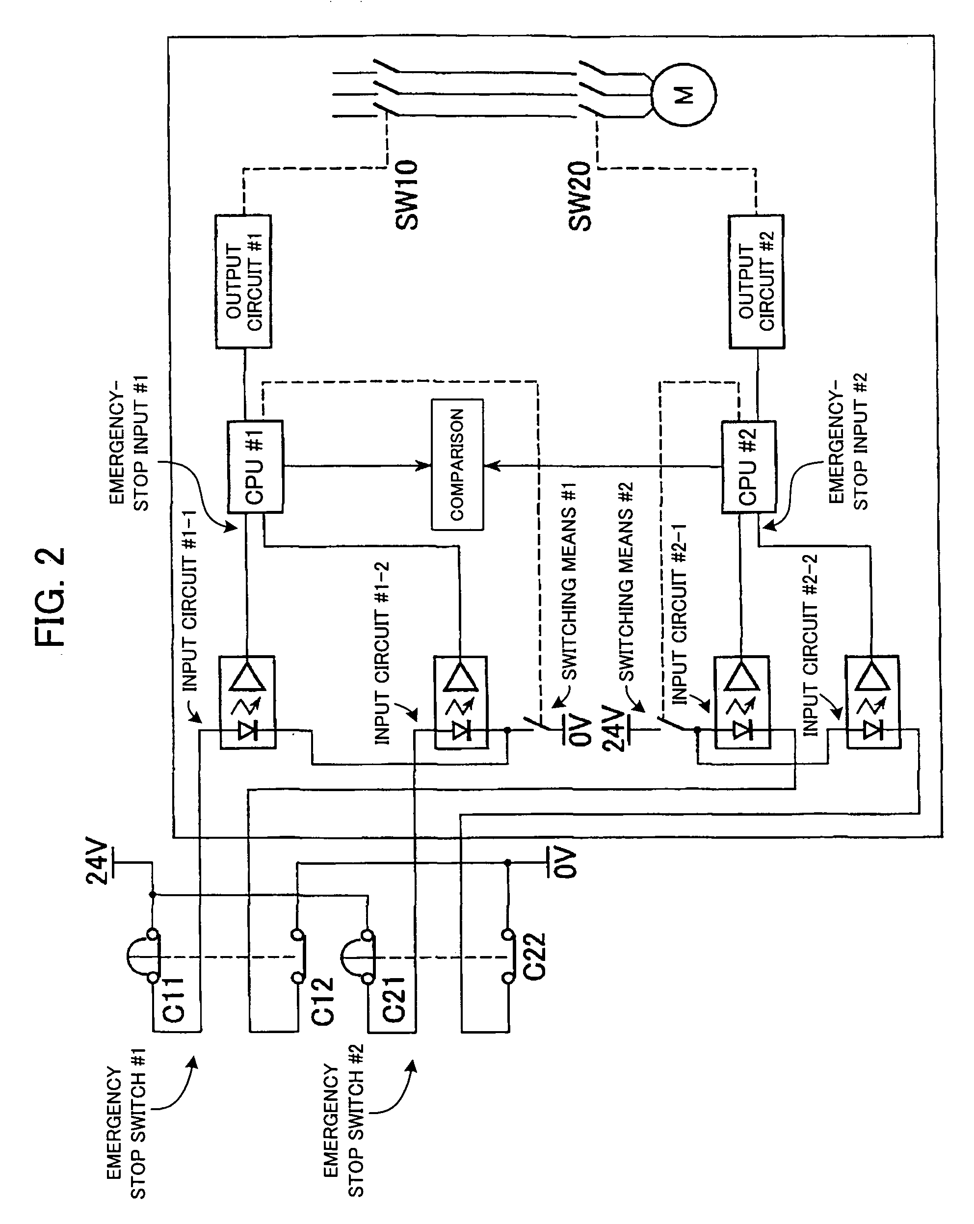
[0028]FIG. 2 shows an example of schematic structure for a device adopting a dualized emergency stop circuit in an embodiment of the invention. In this example of the device, the number of signal systems which generate and transmit an emergency stop signal is two, which is just an example and the number of signal systems can be one or more than two. As an input circuit through which the emergency stop signal comes in, one adopting a photo coupler is shown by way of example.

[0029]As shown in the same drawing, an emergency stop switch section comprises normally-closed emergency stop switches #1 and #2. The number of emergency stop switches corresponds to the number of signal systems (in this example, 2). Corresponding to dualization, the emergency stop switches #1, #2 each have two contacts (C11, C12 and C21, C22) opened and closed in phase, to which two emergency stop input circuits (referred to also simply as “input circuits”) are connected, one-to-one.

[0030]Hence, this example has ...


PUM


Abstract

An emergency-stop device provided in a robot system, a machine tool or the like, arranged to promptly detect failure of a circuit through which an emergency stop signal is supplied to an CPU, without stopping the robot system, the machine tool or the like, to improve reliability. When at least one of emergency stop switches is opened, a CPU #1 or #2 issues an emergency stop command through one of input circuits, so that a switch SW10 or SW20 is opened by an output circuit #1 or #2 to emergency-stop the system. Switching means #1, #2 are opened separately, at appropriate intervals, and change of output of each photo coupler is recognized. In this manner, it is checked that open / closed-state outputs related to contacts C11 and C21 / C12 and C22, each connected to one of the input circuits, indicate an open state. If regarding any of the contacts, change of output of the corresponding photo coupler is not recognized, the system is stopped and an action such as causing a buzzer and displaying of an alarm is taken.

Description

BACKGROUND OF THE INVENTION[0001]1. Field of the Invention[0002]The present invention relates to a device for emergency-stopping a servomotor provided in a robot system, a machine tool controlled by a numerical controller, etc.[0003]2. Description of Related Art[0004]An emergency-stop device including a CPU (central processing unit) is widely used in a robot system or a machine tool controlled by a numerical controller. In this connection, it is a known technique to dualize a emergency stop circuit, considering possible failure of the emergency stop circuit. FIG. 1 shows a typical example of a conventional device including dualized emergency stop circuit. As shown in this drawing, the device includes two CPU's #1, #2, which are connected to an emergency stop switch by separate emergency stop circuits.[0005]When the normally-closed emergency stop switch is depressed, an emergency stop signal (indicating that a contact is open) is supplied to the CPU's #1, #2 through their respective ...

Claims


Application Information

Patent Timeline
Patent Type & Authority Patents(United States)
IPC IPC(8): G05B19/406
CPCG05B19/406G05B2219/50198
Inventor HASHIMOTO, YOSHIKITANABE, YOSHIKIYOCHINO, NOBUO
Owner FANUC LTD
Why Eureka
Try Eureka