Fluxgate sensor integrated in a semiconductor substrate and method for manufacturing the same

a technology of semiconductor substrate and fluxgate sensor, which is applied in the field of fluxgate sensor, can solve the problems of high production cost, large overall size of the system, and high production cost, and achieve the effects of compact size, reduced demagnetizing field property, and low production cos

Active Publication Date: 2007-04-24
SAMSUNG ELECTRONICS CO LTD
View PDF6 Cites 13 Cited by
  • Summary
  • Abstract
  • Description
  • Claims
  • Application Information

AI Technical Summary

Benefits of technology

[0006]In an effort to overcome at least some of the above-mentioned problems, it is a feature of an embodiment of the present invention to provide a high sensitivity fluxgate sensor integrated in a semiconductor substrate capable of not only reducing overall size of a system, but also detecting a magnetic field with greater accuracy, and a method for manufacturing the highly sensitive fluxgate sensor.
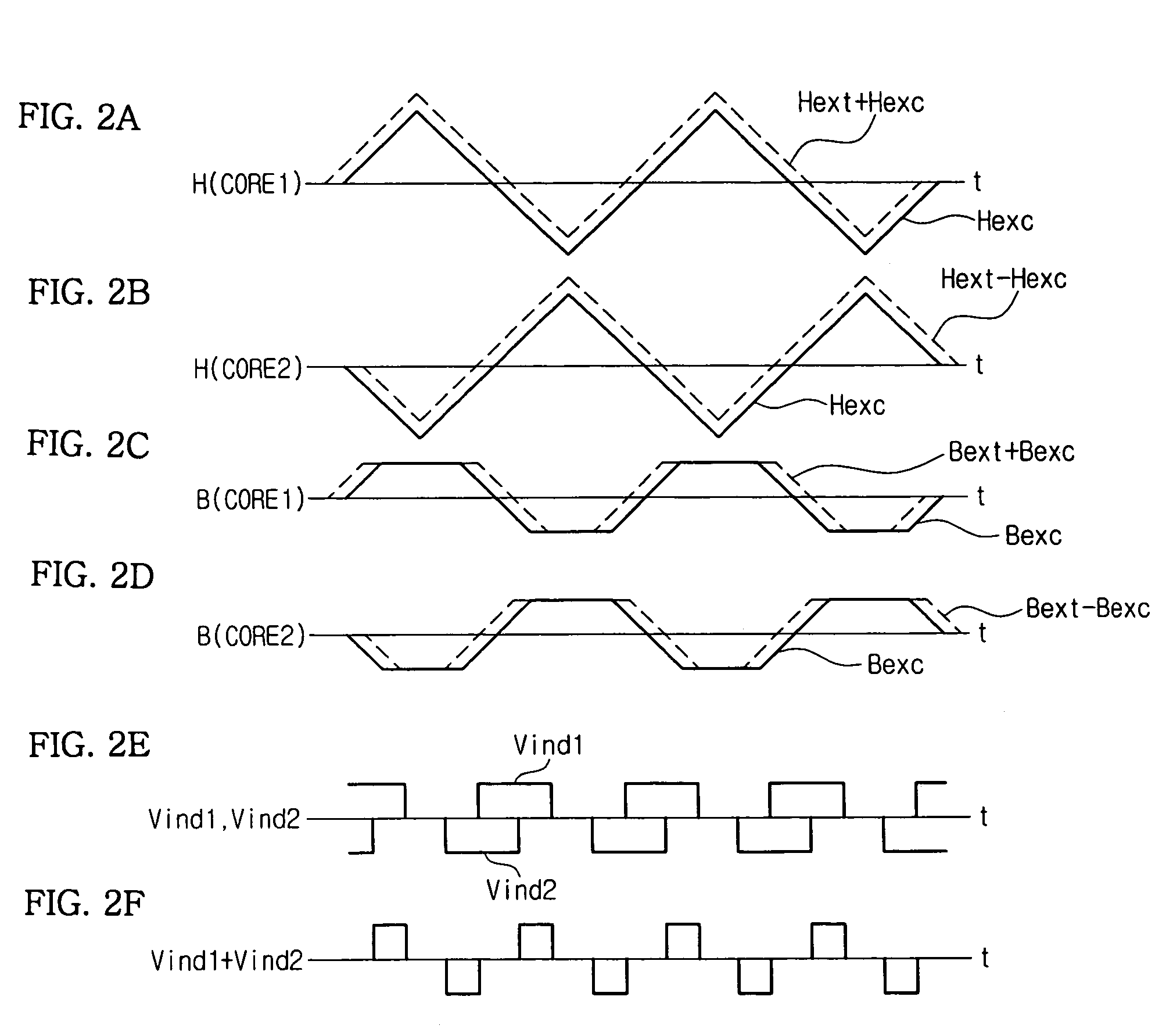
[0007]Another feature of an embodiment of the present invention is to prevent an induction wave in a flux change detecting coil when the external magnetic field is measured as zero (0).
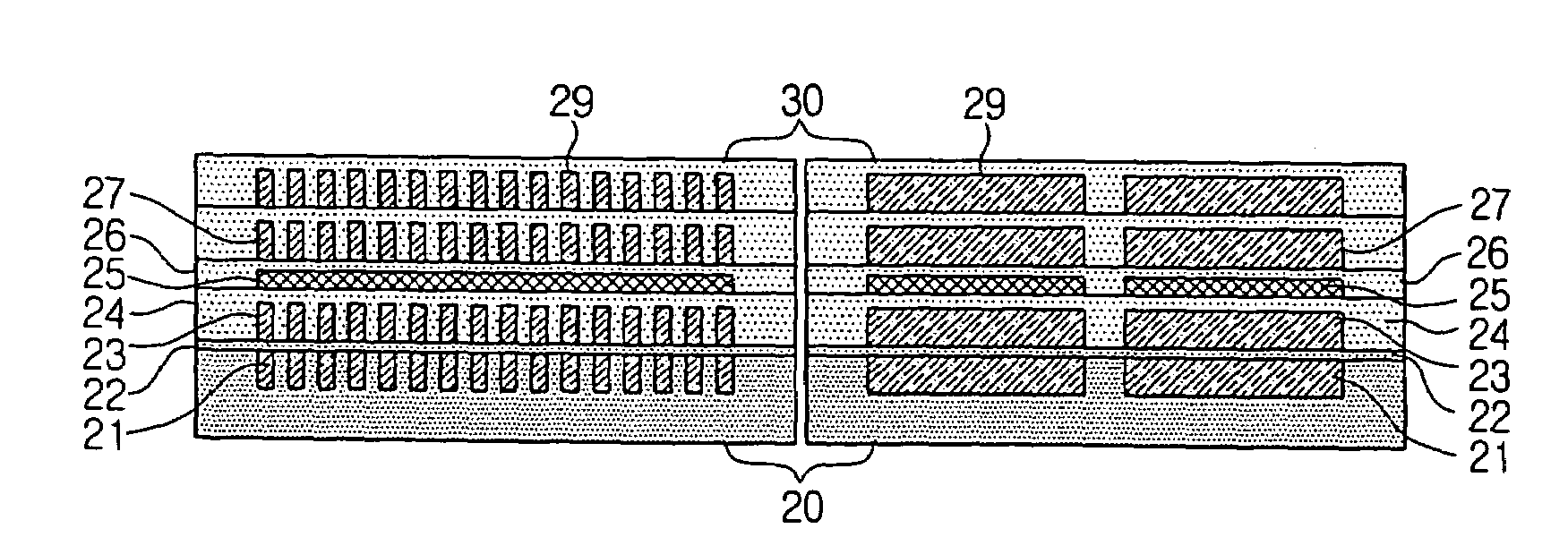
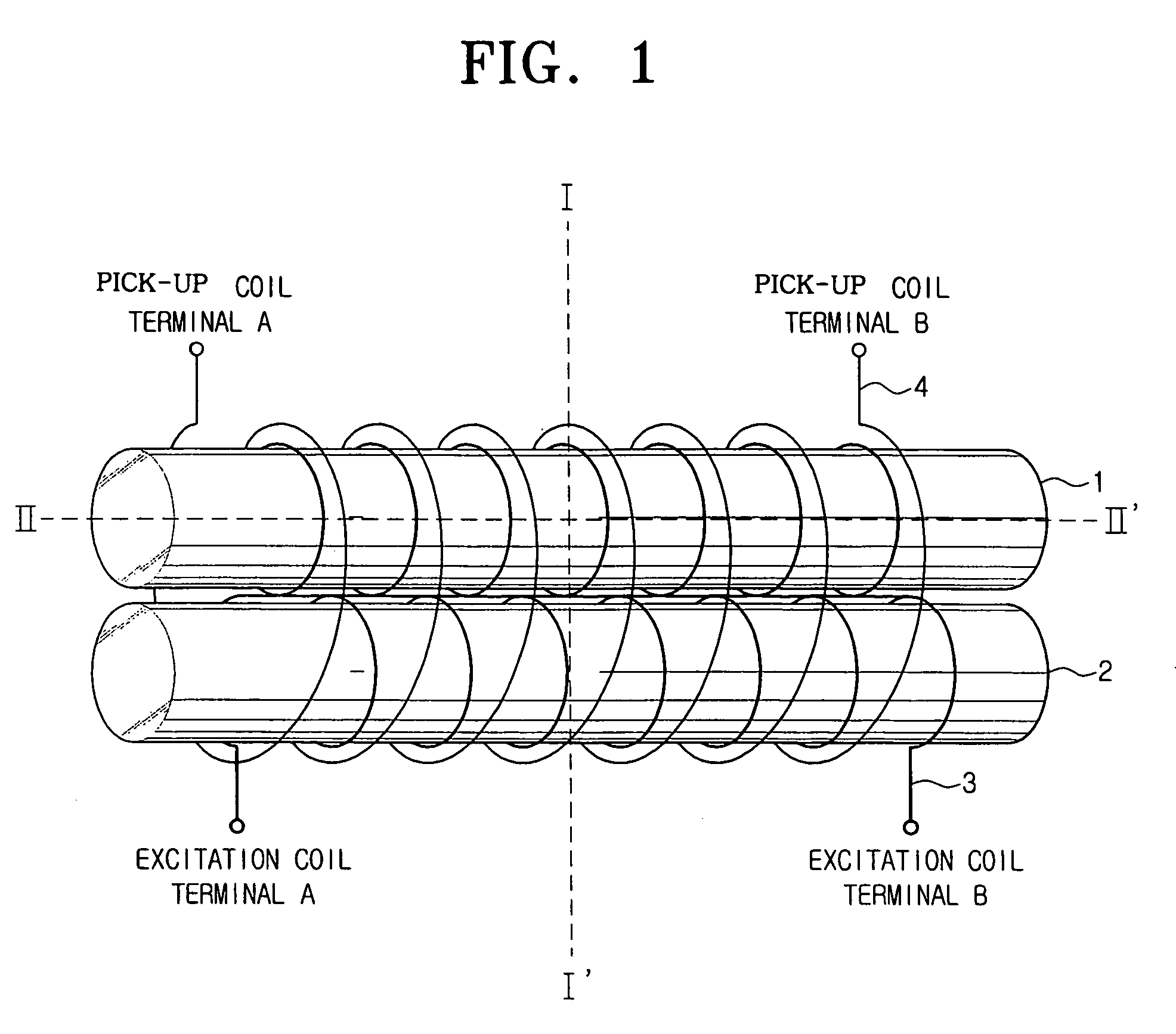
[0015]With a fluxgate sensor integrated in a semiconductor substrate and a manufacturing method thereof according to the embodiments of the present invention, because a soft magnetic core is extended in a direction of magnetic field detection, a demagnetizing field property may be reduced. Further, because the pick-up coil is stacked on the excitation coil that winds the soft magnetic core, no induction waves occur in the pick-up coil. Additionally, the fluxgate sensor according to the embodiments of the present invention has a compact size, consumes little power, and may be easily integrated into various other circuits.

Problems solved by technology

The conventional fluxgate sensor, however, has the following problems, some of which are due to the structure of the conventional fluxgate sensor.
In the structure of a conventional fluxgate sensor, the coil being wound around a large bar-shaped core or annular-shaped core, which is made of soft magnetic ribbon, results in high production costs and a large overall size of the system.
In addition, magnetic flux leakage by the core is inevitable in the flux change generated by an excitation coil.
Accordingly, high sensitivity is not readily achieved.

Method used


Image

  • Fluxgate sensor integrated in a semiconductor substrate and method for manufacturing the same
  • Fluxgate sensor integrated in a semiconductor substrate and method for manufacturing the same
  • Fluxgate sensor integrated in a semiconductor substrate and method for manufacturing the same

Examples


Embodiment Construction

[0029]Korean Application No. 2003-5078, filed Jan. 25, 2003, and entitled: “Fluxgate Sensor Integrated in a Semiconductor Substrate and Method for Manufacturing the Same,” is incorporated by reference herein in its entirety.

[0030]The present invention will now be described more fully hereinafter with reference to the accompanying drawings, in which preferred embodiments of the invention are shown. The invention may, however, be embodied in different forms and should not be construed as limited to the embodiments set forth herein. Rather, these embodiments are provided so that this disclosure will be thorough and complete, and will fully convey the scope of the invention to those skilled in the art. In the drawings, the thickness of layers and regions are exaggerated for clarity. It will also be understood that when a layer is referred to as being “on” another layer or substrate, it can be directly on the other layer or substrate, or intervening layers may also be present. Like refer...


PUM


Abstract

In a fluxgate sensor integrated in a semiconductor substrate and a method for manufacturing the same, the fluxgate sensor includes a soft magnetic core formed on the semiconductor substrate, an excitation coil winding the soft magnetic core and being insulated by first and second insulating layers deposited above and below the soft magnetic core, respectively, and a pick-up coil, winding the soft magnetic core and being insulated by third and fourth insulating layers deposited above and below the excitation coil, respectively.

Description

BACKGROUND OF THE INVENTION[0001]1. Field of the Invention[0002]The present invention generally relates to a fluxgate sensor. More particularly, the present invention relates to a fluxgate sensor integrated in a semiconductor substrate and a method for manufacturing the same.[0003]2. Description of the Related Art[0004]The existence of magnetic energy has been proven through various physical phenomena. For example, a fluxgate sensor enables a human to indirectly perceive magnetic energy since magnetic energy is not perceivable by human sense organs, such as eyes or ears. Regarding a fluxgate sensor, a magnetic sensor employing a soft magnetic body and coil have been conventionally used. A magnetic sensor is made by winding a coil around a relatively large bar-shaped core or annular-shaped core, which is formed of a soft magnetic ribbon. In addition, an electronic circuit is employed to obtain a magnetic field in proportion to the measured magnetic field.[0005]The conventional fluxga...

Claims


Application Information

Patent Timeline
Patent Type & Authority Patents(United States)
IPC IPC(8): G01R33/04G01R33/02G01R33/05H01L43/02
CPCG01R33/04G01R33/05G01R15/185G01R33/02H10N50/80
Inventor PARK, HAE-SEOKSHIM, DONG-SIKCHOI, SANG-ONNA, KYUNG-WON
Owner SAMSUNG ELECTRONICS CO LTD
Why Eureka
Try Eureka