Decorative surface covering with embedded RF antenna and RF shield and method for making the same

a technology of decorative surface covering and conductive antenna, which is applied in the direction of protective material radiating elements, burglar alarm mechanical actuation, instruments, etc., can solve the problems of time-consuming sequential scanning process, system limitations, and poor suitability of bar codes

Active Publication Date: 2007-04-24
WILSONART
View PDF15 Cites 21 Cited by
  • Summary
  • Abstract
  • Description
  • Claims
  • Application Information

AI Technical Summary

Problems solved by technology

Such systems have limitations, however.
For example, such a scanning process requires a time-consuming sequential scanning process, either by hand or by an automated feeder, which allows only one label to be read at a time.
Because of their optic nature, bar codes are poorly suited for harsh environments, such as wet, dirty, oily, or other harsh environments, which might obscure or damage the bar code label.
In addition, bar codes provide only a limited amount of information, usually limited to asset identification.
In addition, RFID tags can be read without human intervention and the delays associated with such intervention.
While this tec

Method used


Image

  • Decorative surface covering with embedded RF antenna and RF shield and method for making the same
  • Decorative surface covering with embedded RF antenna and RF shield and method for making the same
  • Decorative surface covering with embedded RF antenna and RF shield and method for making the same

Examples


example 1

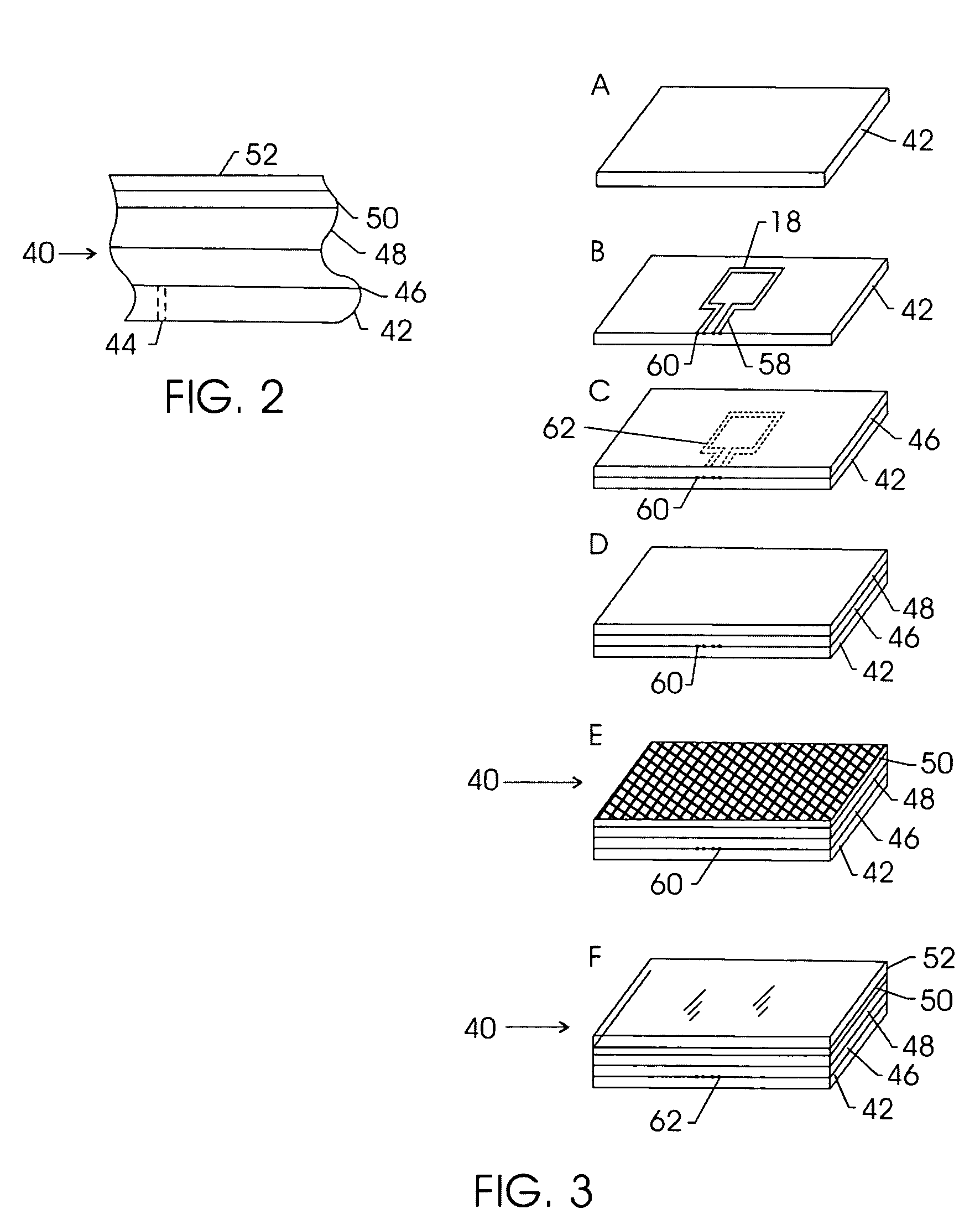
[0049]An open loop antenna as shown in figure XX was prepared by the stencil method. The antennae were 16 inches by 16 inches in a single loop. A first example had a conductor (line) width of 0.25 inches. The phenolic treated kraft sheet with the dry antenna was pressed at 1000 p.s.i. The treated kraft sheet was placed between two aluminum foil sheets and the aluminum foil was placed between two stainless steel plates. This sandwich, containing five layers, was then inserted between the platens of a conventional high-pressure laminating press as is commonly used in the industry. The platens were heated with pressurized hot water. The temperature of the platens was ramped from ambient to 273° F. rapidly and then held at 273° F. so that the total heat applied time above ambient was 22 minutes. At the end of the heating time, and while still under pressure the platens were cooled to ambient temperature. The cooling cycle lasted a total of 12 minutes. The samples were removed from the p...

example 2

[0050]Prepared like example 1, except line width of 0.125 inches.

example 3

[0051]Prepared like example 1, except line width of 0.50 inches.


PUM

PropertyMeasurementUnit
Frequencyaaaaaaaaaa
Frequencyaaaaaaaaaa
Frequencyaaaaaaaaaa

Abstract

A technique is provided for printing an RFID antenna using conductive ink on a substrate and incorporating that substrate as a layer in a decorative surface such as a high pressure decorative laminate. In addition, a technique is provided for incorporating a conductive mesh into a surface, such as a high pressure decorative laminate, to form an RFID shield which prevents stray signals from reaching an RFID antenna. A technique is also provided for integrating both a printed antenna and conductive mesh shield into a single surface, such as a decorative surface, to allow the reading of desired RFID tags while preventing the reading of undesired RFID tags.

Description

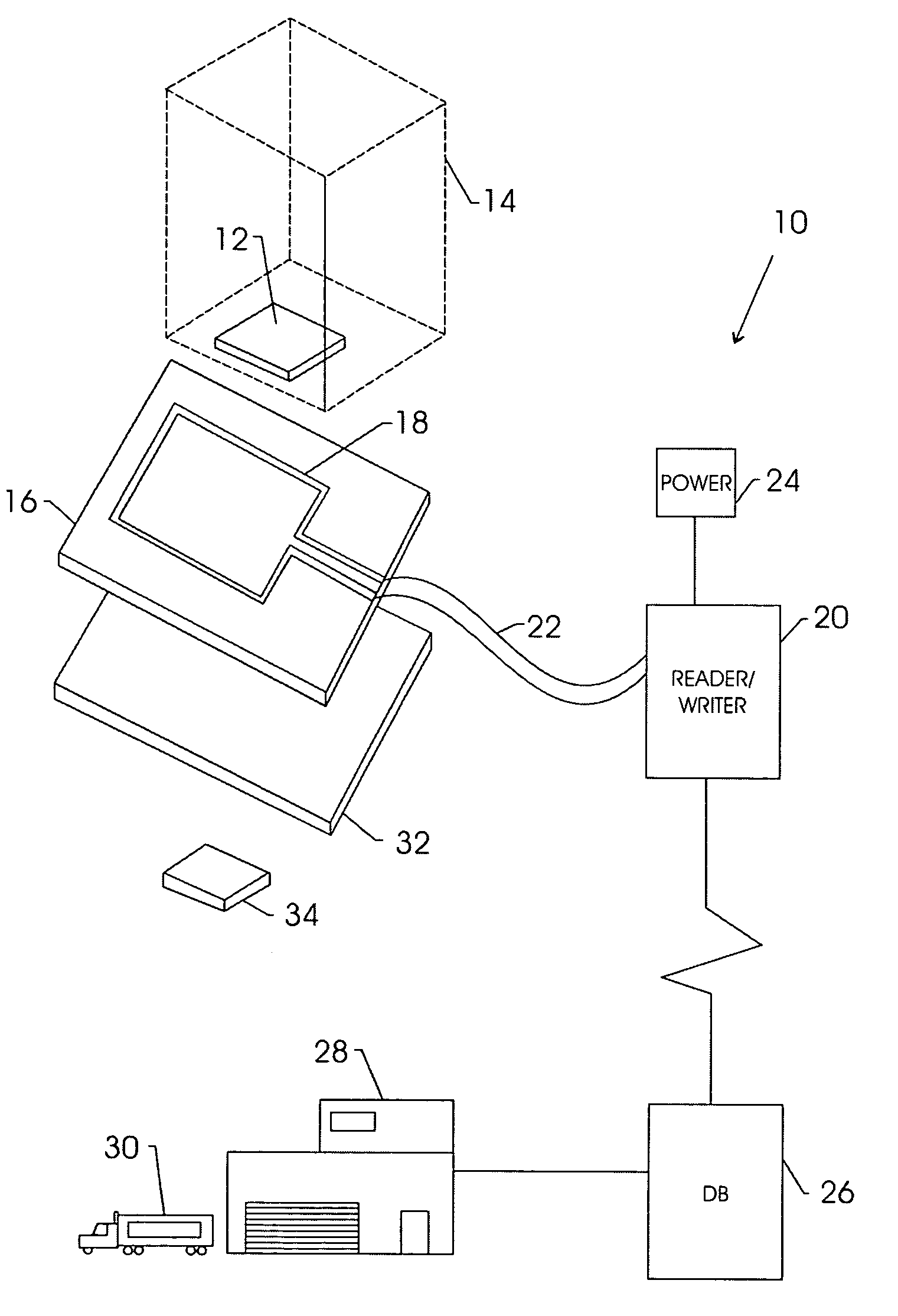
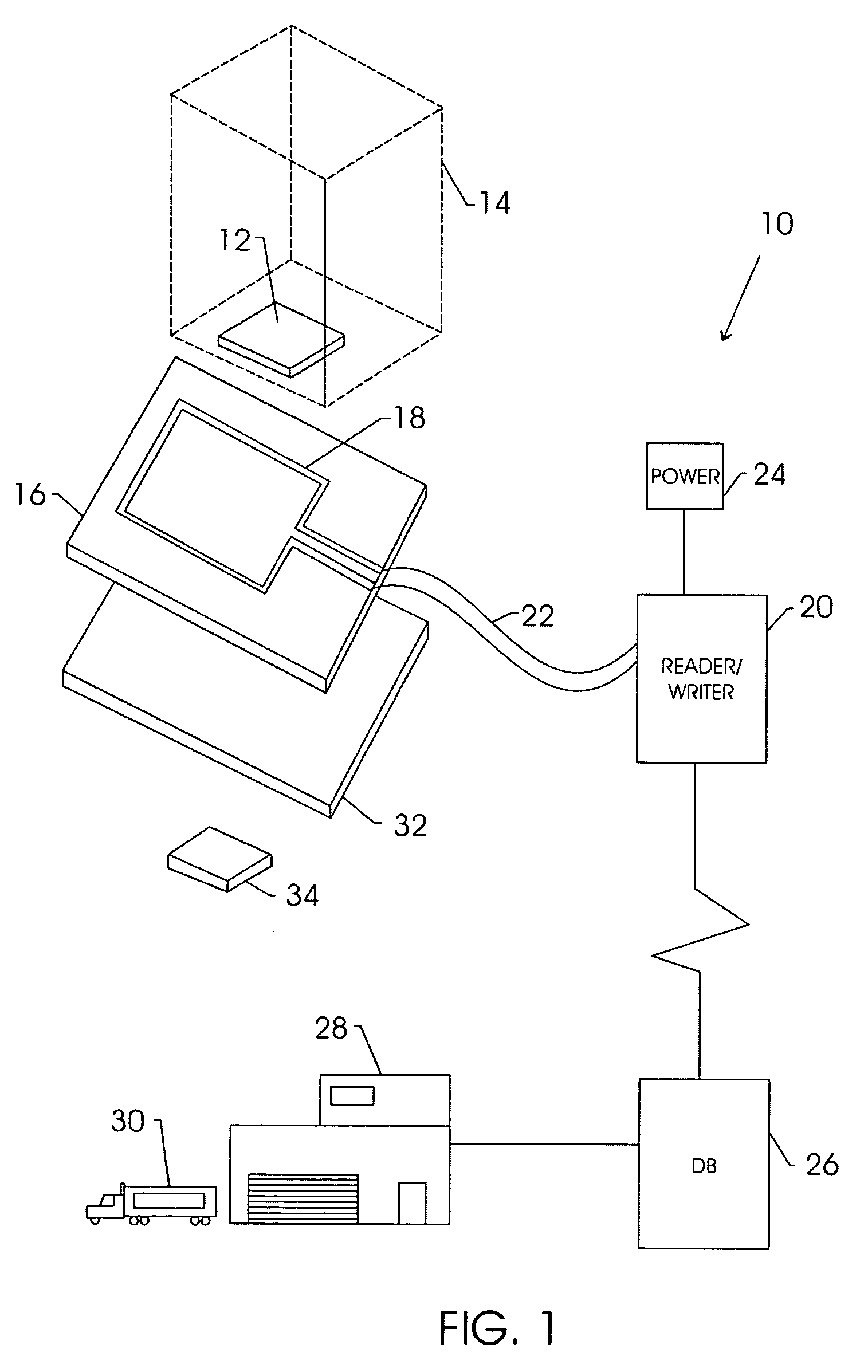
CROSS-REFERENCE TO RELATED APPLICATIONS[0001]The present application is based on and claims priority of U.S. Provisional Patent Application No. 60 / 468,967, filed on May 8, 2003, and entitled DECORATIVE SURFACE COVERING WITH EMBEDDED RF ANTENNA AND RF SHIELD AND METHOD FOR MAKING SAME.BACKGROUND OF THE INVENTION[0002]The present technique relates generally to the formation of antennae or other conductive structures inside a solid medium. More specifically, the present technique relates to the formation of a conductive antenna within a layered structure, such as a decorative surface covering or laminate.[0003]In the field of asset tracking and inventory, various technologies have emerged which improve both the accuracy and speed by which inventories are tracked relative to fully manual techniques. For example, bar code readers may be used to optically read a bar code label on an asset, allowing that label, and presumably the asset, to be identified automatically by reference to a data...

Claims


Application Information

Patent Timeline
IPC IPC(8): G08B13/14B42D15/10G06K7/00G06K7/08G06K17/00H01Q1/38H01Q1/40H01Q1/44H01Q1/52H01Q7/04
CPCG06K7/0008G06K7/10336H01Q1/526H01Q1/44Y10T428/24802
Inventor KREBS, ROBERT R.
Owner WILSONART
Why Eureka
Try Eureka