Heat dissipation device incorporating fan duct

a technology of fan ducts and heat dissipation devices, which is applied in the direction of lighting and heating apparatus, liquid fuel engines, instruments, etc., can solve the problems of destabilizing operation, complicated and costly to mount a fan duct, and achieve the effect of preventing the flow of cooling air and preventing the formation of turbulent flow

Inactive Publication Date: 2007-04-24
HON HAI PRECISION IND CO LTD
View PDF10 Cites 67 Cited by
  • Summary
  • Abstract
  • Description
  • Claims
  • Application Information

AI Technical Summary

Benefits of technology

[0008]To achieve the above-mentioned object, a heat dissipation device in accordance with the present invention comprises two heat sinks mounted on two electronic components which is mounted within a server, two fans mounted on a mounting plate of the server facing the heat sinks for blowing cooling air to the heat sinks, and a fan duct. The fan duct comprises a top plate, a pair of side plates extending from opposite sides of the top plate, a pair of partition walls extending from middle portions of the top plate, and a stop wall connected between ends of the partition walls. The fan duct is hermetically connected to the mounting plate and the bottom plate thereby cooperatively forming a sealed passage therebetween. The passage comprises an inlet adjacent the fans and two separate outlets between the side plates and the partition walls respectively for accommodating the heat sinks therein. The partition walls and the stop wall can prevent cooling air flow from the fans leaking from space between the heat sinks and prevent producing turbulent flow at the outlets of the fan duct.

Problems solved by technology

Electronic devices such as central processing units (CPUs) frequently generate large amounts of heat during normal operation, which can destabilize operation and cause damage.
However, in some special computer systems, space for the heat dissipation assembly is limited.
It becomes complicated and costly to mount a fan duct for each combination of a heat sink and a fan with the computer system.

Method used


Image

  • Heat dissipation device incorporating fan duct
  • Heat dissipation device incorporating fan duct
  • Heat dissipation device incorporating fan duct

Examples


Embodiment Construction

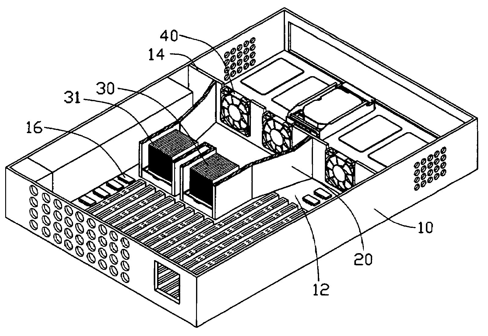
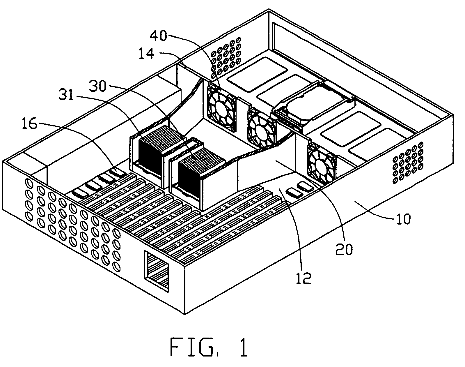
[0013]Referring to the attached drawings, FIG. 1 shows a heat dissipation device in accordance with the present invention within a server 10. The server 10 comprises a bottom plate 12 and a mounting plate 14 extending perpendicularly from the bottom plate 12. The server 10 has a plurality of electronic components 16, such as: wafers, installed on a printed circuit board of the bottom plate 12.

[0014]The heat dissipation device comprises a pair of heat sinks 30, a fan duct 20, and a pair of fans 40. The pair of heat sinks 30 are mounted on a pair of respective wafers 16. The heat sink 30 comprises a plurality of fins defining a plurality of channels 31 therebetween. The pair of fans 40 are mounted on the mounting plate 14 aligning with the respective heat sinks 30.

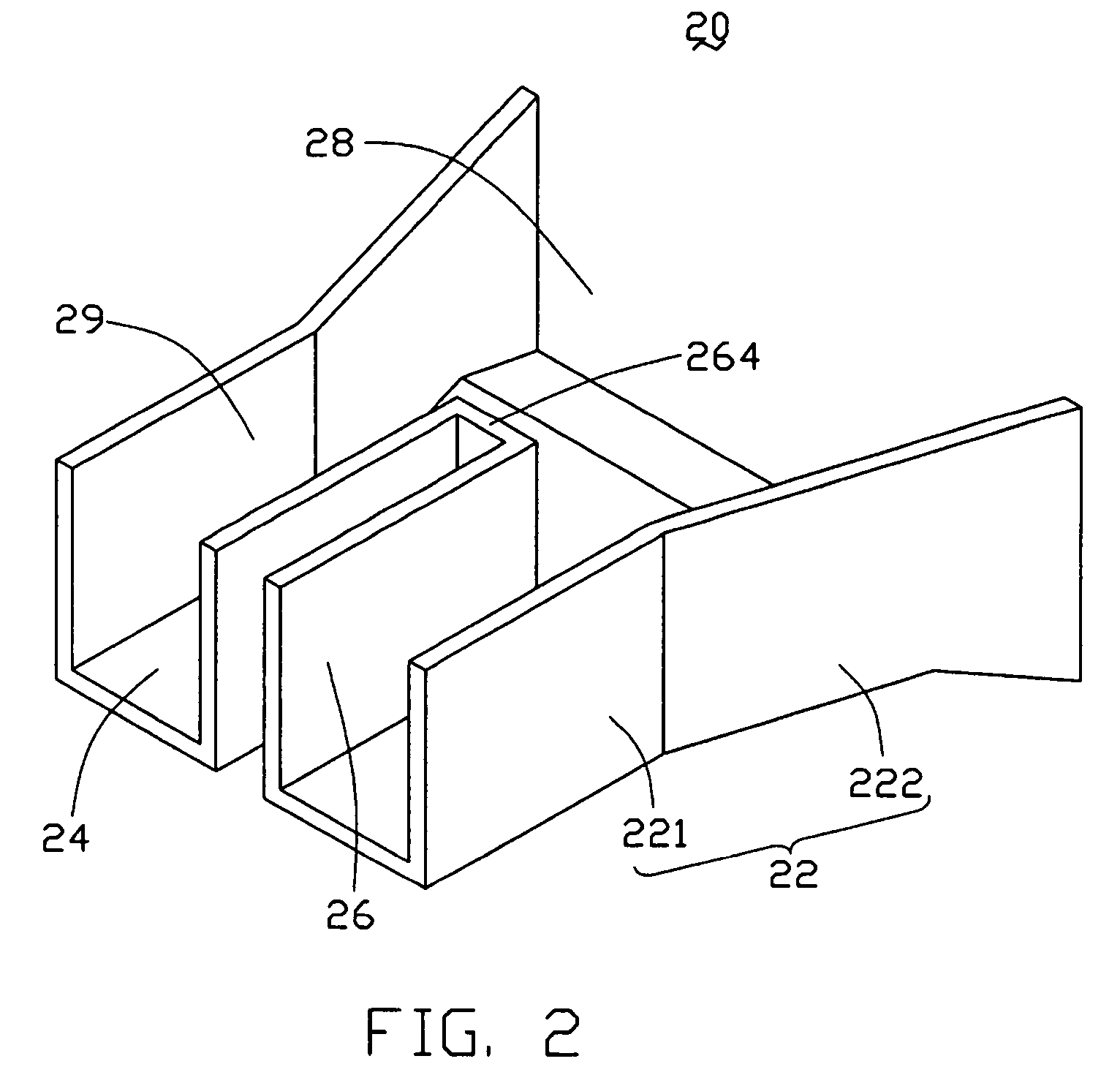
[0015]Referring to FIGS. 2 and 3, the fan duct 20 comprises a top plate 24, a pair of side plates 22 extending perpendicularly from opposite side edges of the top plate 24, and a pair of spaced partition walls 26 extending p...


PUM


Abstract

A heat dissipation device includes two heat sinks (30) mounted on two electronic components (16) which is mounted within a server (10), two fans (40) mounted on a mounting plate (14) of the server facing the heat sinks for blowing cooling air to the heat sinks, and a fan duct (20). The fan duct includes a top plate (24), a pair of side plates (22) extending from opposite sides of the top plate, a pair of partition walls (26) extending from a middle portion of the top plate, and a stop wall (264) connected between ends of the partition walls. The fan duct is hermetically connected to the mounting plate and the bottom plate thereby cooperatively forming a sealed passage therebetween. The passage includes an inlet (28) adjacent the fans and two separate outlets (29) between the side plates and the partition walls respectively for accommodating the heat sinks therein.

Description

BACKGROUND OF THE INVENTION[0001]1. Field of the Invention[0002]The present invention relates to a fan duct, and particularly to a fan duct corresponding to a plurality of heat sinks.[0003]2. Related Art[0004]Electronic devices such as central processing units (CPUs) frequently generate large amounts of heat during normal operation, which can destabilize operation and cause damage. Oftentimes, a heat dissipation assembly is used to dissipate heat from the electronic device. The heat dissipation assembly frequently comprises a fan facilitating removal of heat from the electronic device.[0005]Conventionally, a heat sink is mounted on a CPU inside a computer system The fan is directly mounted on the heat sink. The fan generates currents of air flowing through the heat sink, causing heat to be dissipated into the surrounding air. However, in some special computer systems, space for the heat dissipation assembly is limited. So, a kind of heat dissipation assembly incorporating a heat sin...

Claims


Application Information

Patent Timeline
Patent Type & Authority Patents(United States)
IPC IPC(8): G06F1/20H05K7/20
CPCH05K7/20727
Inventor CHEN, CHIN HUI
Owner HON HAI PRECISION IND CO LTD
Why Eureka
Try Eureka