
System and method for providing remote monitoring of voltage power transmission and distribution devices

a technology for power transmission and distribution devices, applied in process and machine control, digital computer details, instruments, etc., can solve problems such as confined locations, high voltage exposure of technicians, and proximity to hazardous high voltages

Active Publication Date: 2007-04-24
POWER MONITORS
View PDF9 Cites 163 Cited by
  • Summary
  • Abstract
  • Description
  • Claims
  • Application Information

AI Technical Summary

Benefits of technology

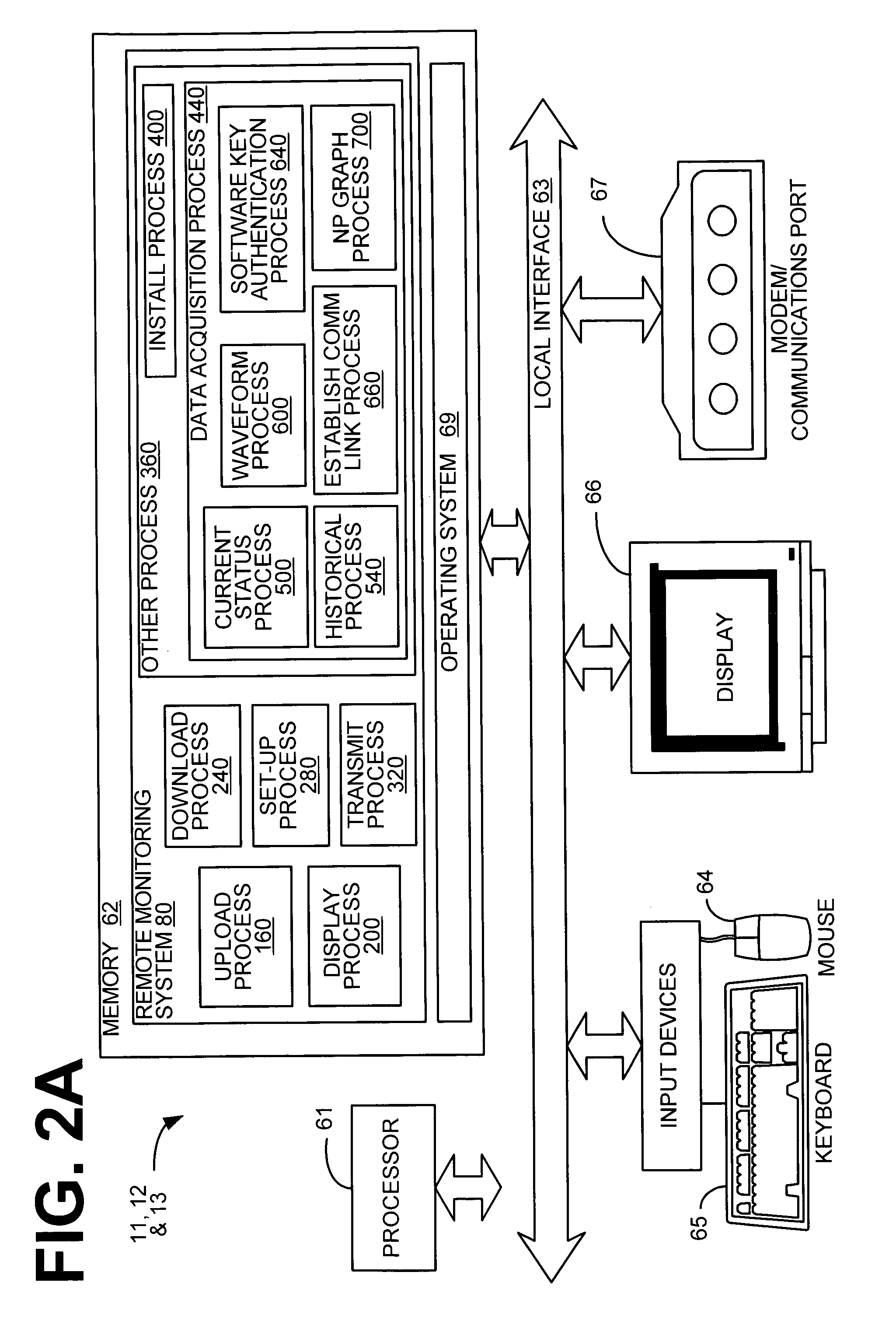
"The present invention is a system and method for remotely monitoring a power device or power delivery system. The system includes a service device with transceiver circuitry to receive power condition information from the power device and computation circuitry to compute an electrical value for the power device. The service device also has display circuitry to display the computed electrical value along with operational parameters of the power device. The technical effect of this invention is to provide a convenient and efficient way to monitor power devices remotely, which can help to prevent power failures and improve overall operational efficiency."

Problems solved by technology

This creates serious safety concerns for both the technician user, and for the manufacturer.
Safety issues include proximity to hazardous high voltages, technician exposure to confined locations (e.g. underground vaults), explosive atmospheres, etc.
Since this may disrupt electrical service to a large area, this is often impractical.
In addition, the large size of existing recorders, and the necessity for physical access to it later, can make it difficult to enclose and lock such conventional analyzing equipment in an electrical panel or transformer case.
Obviously, this creates unsafe conditions by putting the technician and others at great risk of electrocution.
Also, safe voltage isolation has been difficult to achieve in a small recorder when all voltage channels are to be brought into a single recorder unit.
This is extremely difficult to achieve at voltages as high as 600 Volts.
Thus, heretofore an unaddressed need exists in the industry to address the aforementioned deficiencies quickly and efficiently.

Method used


Image

  • System and method for providing remote monitoring of voltage power transmission and distribution devices
  • System and method for providing remote monitoring of voltage power transmission and distribution devices
  • System and method for providing remote monitoring of voltage power transmission and distribution devices

Examples


Embodiment Construction

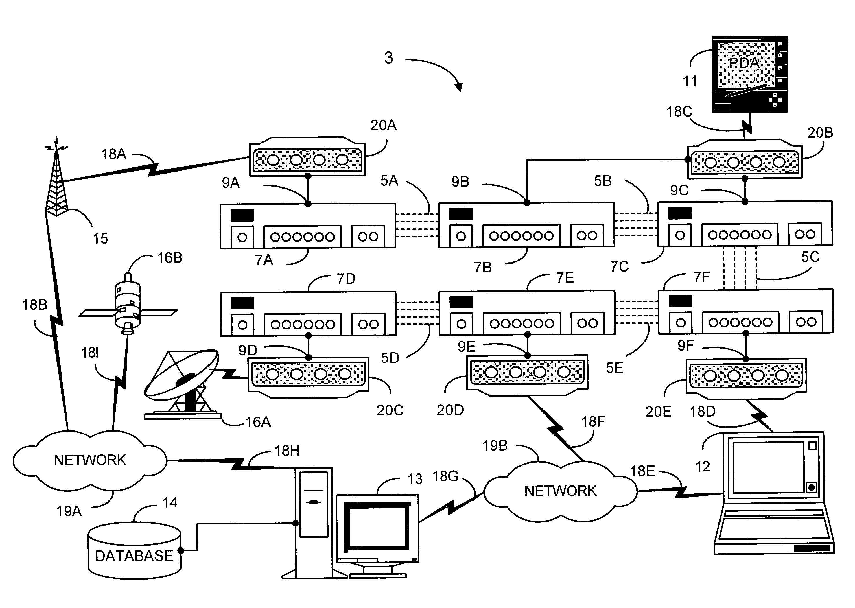
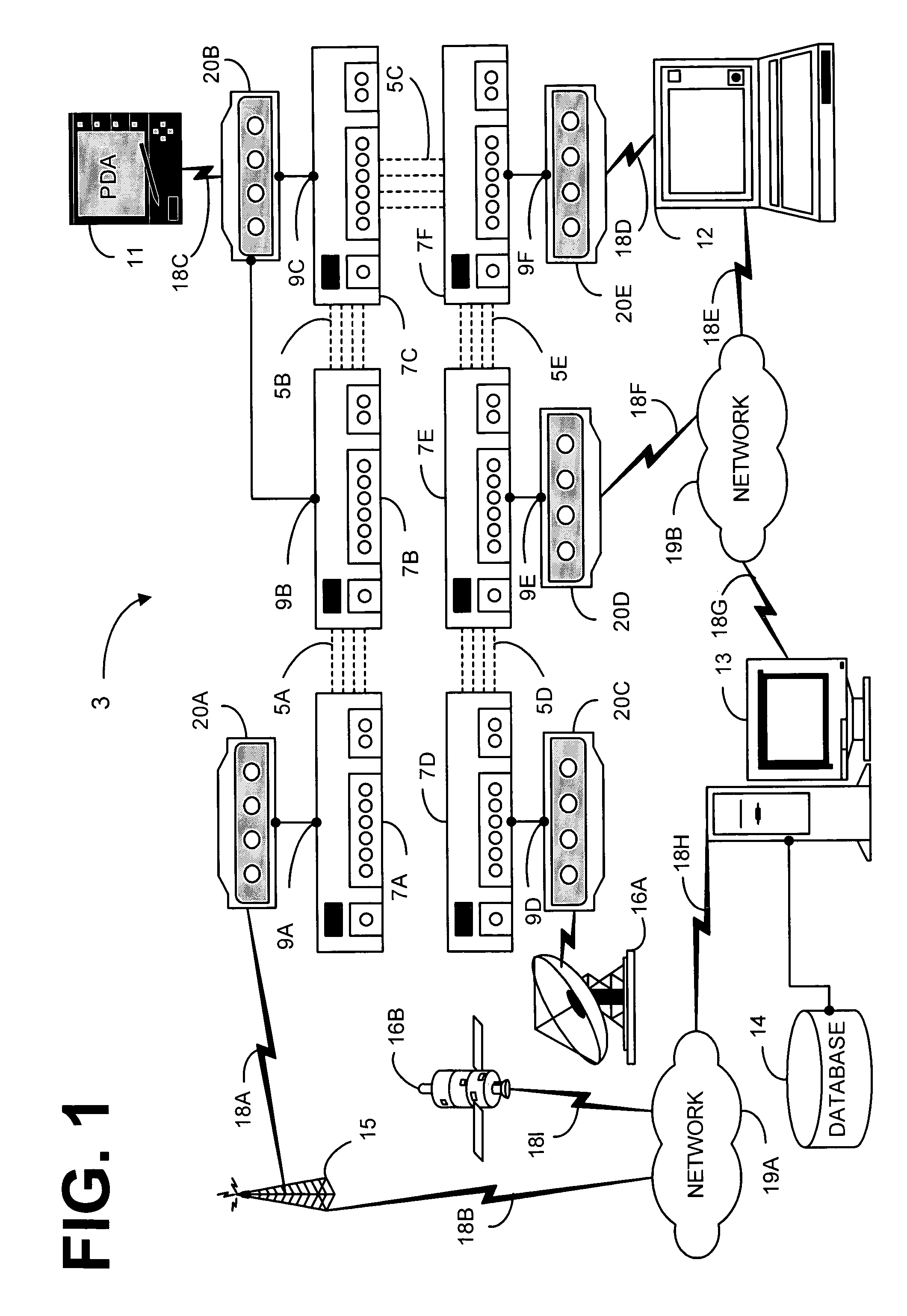
[0061]The present invention solves many problems, while it delivers accuracy and provides the user with much greater flexibility over conventional arrangements. The present invention relates to power analyzers for use in the field in monitoring power transmission and distribution systems.

[0062]In particular, the present invention relates to a small, wireless, remote power monitoring system. The remote power monitoring system is capable of independently sensing and recording voltage and current conditions, including but not limited to performance conditions and external environmental conditions. The remote power monitoring system performing in a larger system collects, and records voltage and current conditions detected by one or more transducers in accordance with the invention. These larger systems, include but are not limited to, network protectors, circuit breakers, electrical panels, transformers, reclosers, capacitor banks, fuses, transfer switches, voltage regulators, VAR comp...


PUM


Abstract

The present invention provides a system and method for providing remote monitoring of a power device. In architecture, the system includes a service device that includes a transceiver circuitry to receive information of a power condition from the power device, and a computation circuitry to compute an electrical value for the power device. In addition, the service device includes a display circuitry that displays the computed electrical value in conjunction with operational parameters of the power device. The present invention can also be viewed as a method for providing remote monitoring of a power device. The method operates by detecting a power condition of the power device, and computing an electrical value for the power device. The electrical value computed in conjunction with the operational parameters is then displayed.

Description

CROSS-REFERENCE TO RELATED APPLICATIONS[0001]This application claims the benefit of U.S. patent application Ser. No. 10 / 920,460, filed on Aug. 18, 2004, entitled “A SYSTEM AND METHOD FOR PROVIDING REMOTE MONITORING OF VOLTAGE POWER TRANSMISSION AND DISTRIBUTION DEVICES”, and U.S. patent application Ser. No. 60 / 508,380, filed on Oct. 6, 2003, entitled “A SYSTEM AND METHOD FOR PROVIDING REMOTE MONITORING OF VOLTAGE POWER TRANSMISSION AND DISTRIBUTION DEVICES” both of which is incorporated by reference herein in its entirety.COPYRIGHT NOTICE[0002]A portion of the disclosure of this patent document may contain material, which is subject to copyright protection. The copyright owner has no objection to the facsimile reproduction by anyone of the patent document or patent disclosure as it appears in the U.S. Patent and Trademark Office patent file or records, but otherwise reserves all copyright rights whatsoever.TECHNICAL FIELD[0003]The present invention relates to a method and system for...

Claims


Application Information

Patent Timeline
Patent Type & Authority Patents(United States)
IPC IPC(8): G06F19/00G01R31/36G05BG06F1/26
CPCG01R19/2513
Inventor CURT, WALTERMULLINS, CHRISSHOMO, GLENBRUFFY, WAYNE
Owner POWER MONITORS
Learn More