Variable air intake pipe length

a technology of air intake pipe and variable length, which is applied in the direction of internal combustion piston engine air intake, combustion air/fuel air treatment, fuel intake, etc., can solve the problems of increasing the torque of the engine at low engine speed, requiring additional room to effect movement, and involving several moving parts, etc., and achieves the effect of simple manner

Inactive Publication Date: 2007-05-01
BRP POWERTRAIN
View PDF29 Cites 5 Cited by
  • Summary
  • Abstract
  • Description
  • Claims
  • Application Information

AI Technical Summary

Benefits of technology

[0009]An aspect of embodiments of the invention provides an air intake system for an internal combustion eng

Problems solved by technology

This results in an increase of the engine torque at low engine speed.
These prior art devices require

Method used


Image

  • Variable air intake pipe length
  • Variable air intake pipe length
  • Variable air intake pipe length

Examples


Embodiment Construction

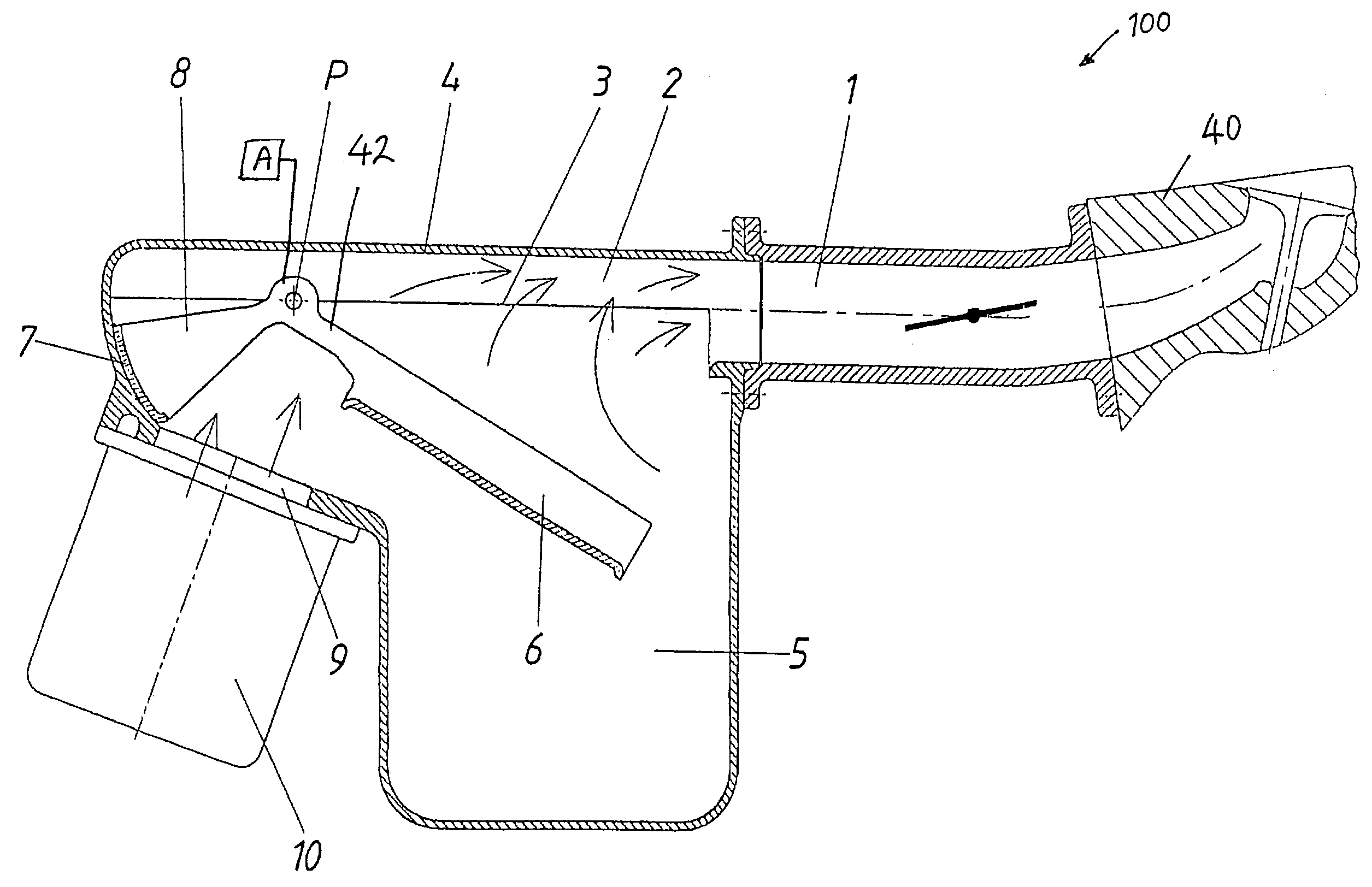
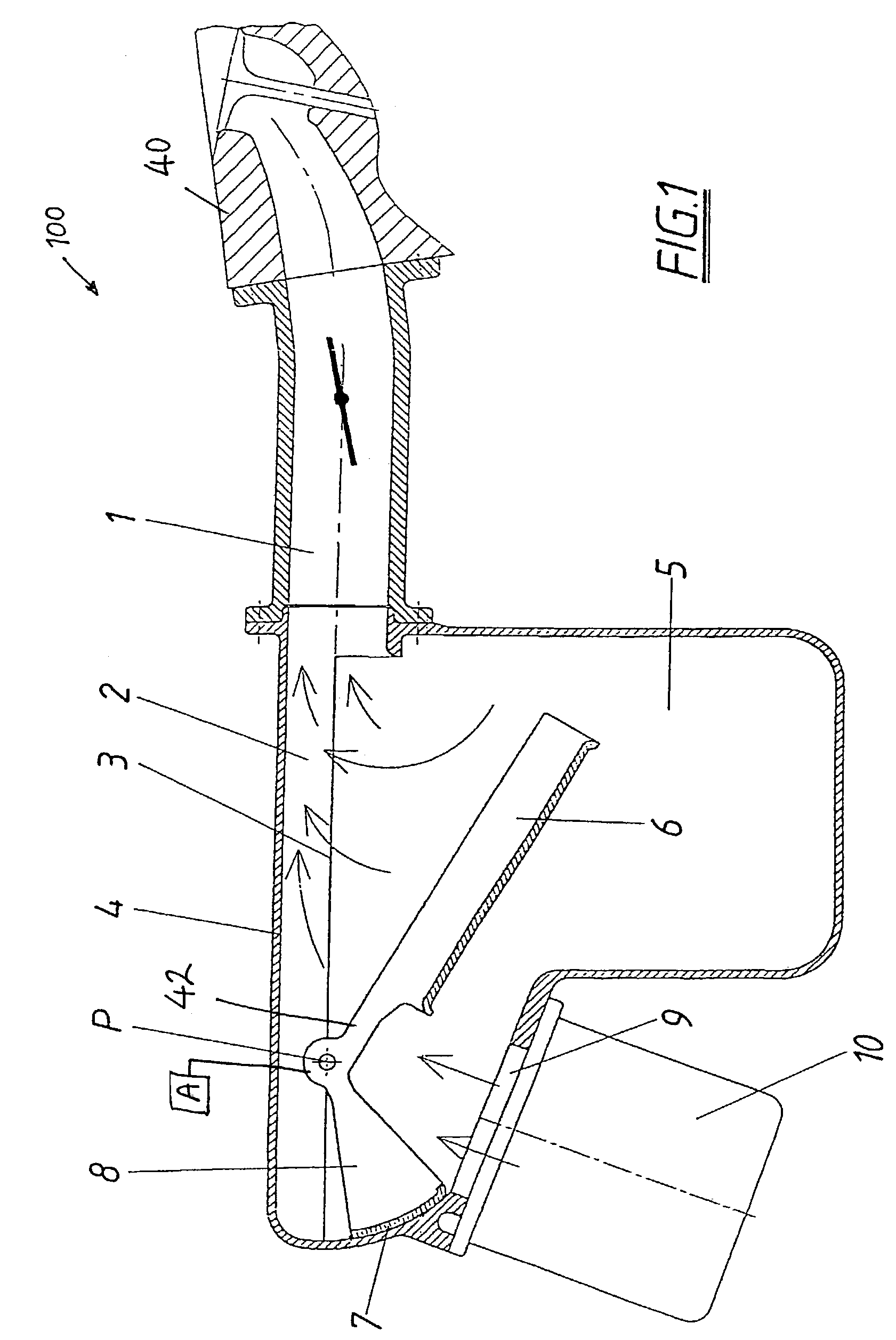
[0030]The present invention is described in a greater detail below with reference to the accompanying drawings which illustrate preferred embodiments of the invention. The invention is described as part of an internal combustion engine. The type of engine is not limited and it should be understood that the air intake concepts disclosed herein as the invention can be applied to any type of air intake system in which it is desired to vary the volume of air taken in.

[0031]FIG. 1 shows an air intake system 100 that forms part of an internal combustion engine. The air intake system 100 includes an air box 5 that is connected to a suction pipe 1 at its upper end 2 as seen in FIG. 1. The suction pipe 1 extends from air box 5 along an axis 3 and forms part of the air box 5. As is known, the suction pipe 1 connects to the cylinder case or head 40 of the engine to supply air for the combustion process.

[0032]Suction pipe 1, as seen in FIG. 1, has a portion integral with the upper end 2 of the ...


PUM


Abstract

An air intake system for an internal combustion engine has at least one air box and a short duct for each cylinder. Each duct can be extended to provide higher torque at low speed. At high speed, the shorter duct length can be selectively provided for enhanced engine performance.

Description

[0001]The present application claims priority to U.S. Provisional Application Ser. No. 60 / 380,868, which was filed on May 17, 2002, the entirety of which is hereby incorporated into the present application by reference.BACKGROUND OF THE INVENTION[0002]1. Field of the Invention[0003]The present invention relates to an air induction system of an internal combustion engine. More particularly, the invention relates to varying the length of an intake pipe of an air intake system of an engine. The invention also relates to varying the intake volume of the intake system of the engine.[0004]2. Discussion of Related Art[0005]As is conventionally known, combustion engines take in air to mix with fuel to provide the combustion that fires the engine. Performance of combustion engines can be varied by changing a number of variables, including the amount of air taken in and the path through which the air travels. One way to enhance engine performance is to increase the volume of air taken in by t...

Claims


Application Information

Patent Timeline
IPC IPC(8): F02M35/10F02B27/02
CPCF02B27/02F02M35/10065F02M35/162F02M35/167Y02T10/146F02B27/0247F02B27/0263F02B27/0231F02B27/0215Y02T10/12
Inventor KORENJAK, NORBERTKUSEL, HEINZ
Owner BRP POWERTRAIN
Why Eureka
Try Eureka