
Microvalve device suitable for controlling a variable displacement compressor

a variable-diameter compressor and micro-valve technology, which is applied in the direction of machines/engines, positive-diameter liquid engines, transducers, etc., can solve the problems of solenoid-assisted cv's, high difficulty in proper operation of variable-position solenoid, and cut off the flow of cool air to the passenger compartmen

Active Publication Date: 2007-05-01
DUNAN MICROSTAQ
View PDF14 Cites 42 Cited by
  • Summary
  • Abstract
  • Description
  • Claims
  • Application Information

AI Technical Summary

Benefits of technology

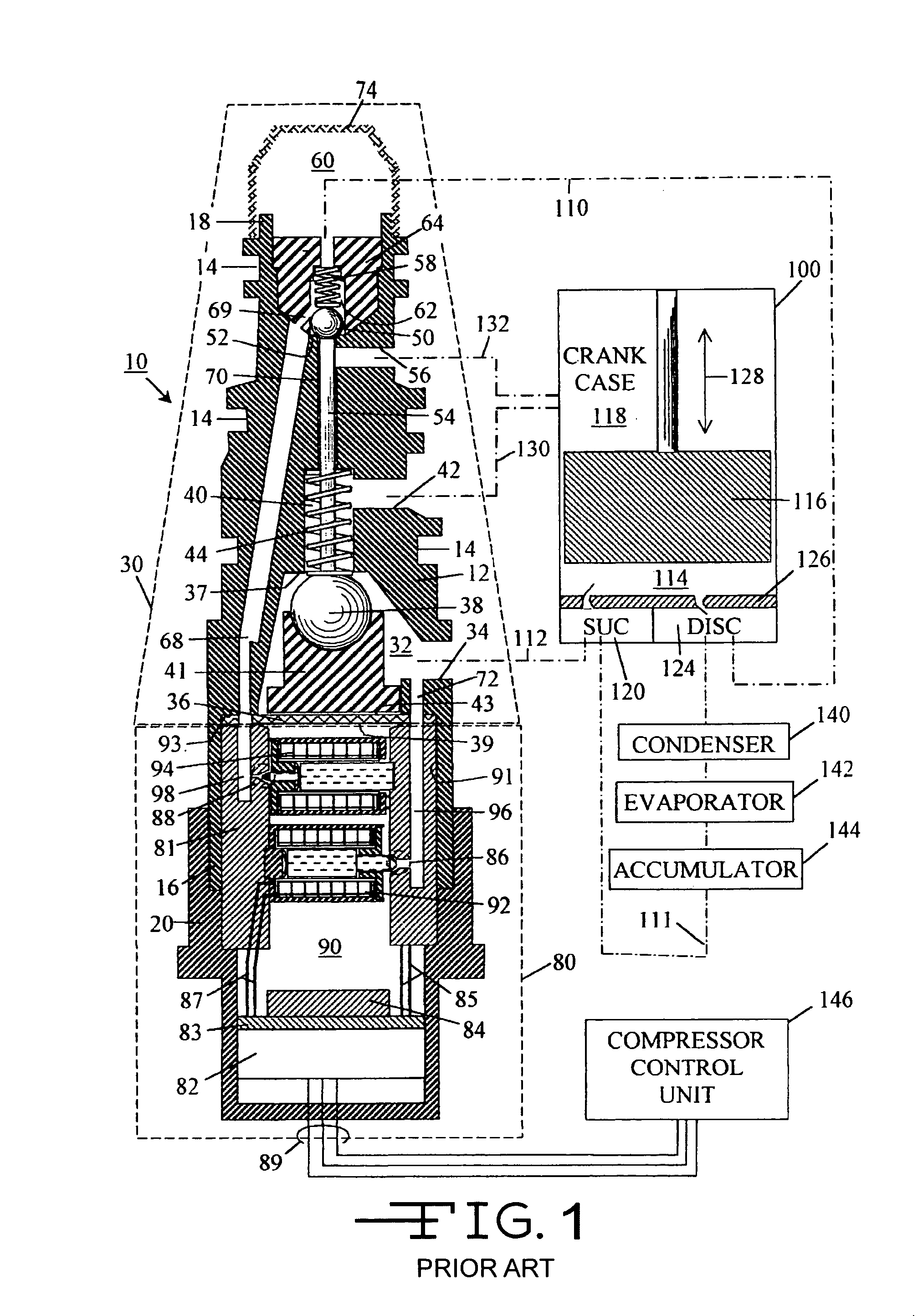
"The present invention is about a control device for a variable displacement compressor. It includes a microvalve operated control valve that maintains the pressure in the compressor crankcase in response to the suction pressure of the compressor relative to a stable, predetermined set-point of the suction pressure, which set-point can be changed during compressor operation by electrical signals. The technical effect of this invention is to provide a more efficient and effective control valve for variable displacement compressors, which ensures stable operation and performance under various operating conditions."

Problems solved by technology

If there is too much heat absorption by the gas within the evaporator, the water found on the fins and tubes through condensation of water vapor from air passing over the evaporator will freeze up, choking off air flow through the evaporator, thereby cutting off the flow of cool air to the passenger compartment.
First, the system is always working at its maximum capacity at the evaporator requiring maximum energy use by the compressor when the cooling system is operating.
There are several major disadvantages with the prior art solenoid-assisted CV's.
Variable position solenoids are not linear in performance and the extreme temperatures in an automobile engine compartment make proper operation of the variable position solenoid highly difficult given power constraints.
Second, a large and precise current value is required to properly position the solenoid.
Third, variable position solenoid systems do not provide a steady suction pressure set-point whereby the cooling system can maintain itself in a state of equilibrium.
A large closing force might require a physically large actuator or require excessive power to maintain the inlet valve in a closed state.

Method used


Image

  • Microvalve device suitable for controlling a variable displacement compressor
  • Microvalve device suitable for controlling a variable displacement compressor
  • Microvalve device suitable for controlling a variable displacement compressor

Examples


Embodiment Construction

[0120]In the following description of the invention, certain terminology will be used for the purpose of reference only, and are not intended to be limiting. Terms such as “upper”, “lower”, “above”, “below”, “rightward”, “leftward”, “clockwise”, and “counterclockwise” refer to directions in the drawings to which reference is made. Terms such as “inward” and “outward” refer to directions toward and away from, respectively, the geometric center of the component described. Terms such as “front”, “rear”, “side”, “leftside”, “rightside”, “top”, “bottom”, “horizontal”, and “vertical” describe the orientation of portions of the component within a consistent but arbitrary frame of reference which is made clear by reference to the text and the associated drawings describing the component under discussion. Such terminology will include the words specifically mentioned above, derivatives thereof, and words of similar import.

[0121]An embodiment of the present invention is illustrated in FIGS. 1...


PUM


Abstract

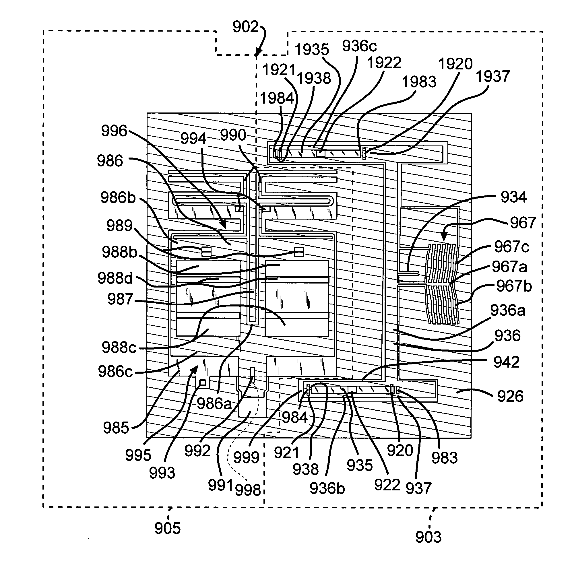
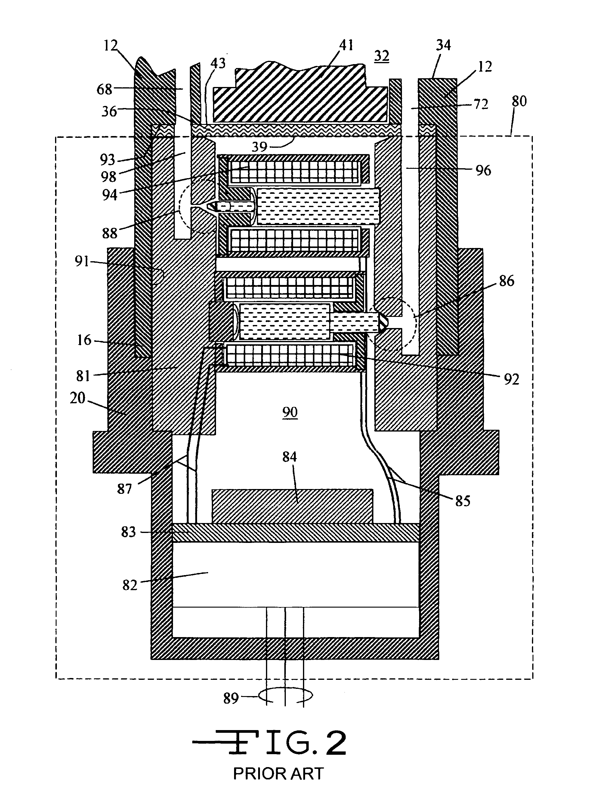
A device is disclosed for controlling a variable displacement compressor. The device comprises a microvalve operated control valve. A microvalve device for controlling fluid flow and a micro spool valve for use as a microvalve are also disclosed.

Description

CROSS-REFERENCE TO RELATED APPLICATIONS[0001]This application is a continuation of International Application No. PCT / US2004 / 039517, filed Nov. 24, 2004, which claims priority from U.S. Provisional Application No. 60 / 525,224, filed Nov. 24, 2003 and U.S. Provisional Application No. 60 / 559,355, filed Apr. 2, 2004. The disclosures of all three applications are incorporated herein by reference.STATEMENT REGARDING FEDERALLY SPONSORED RESEARCH OR DEVELOPMENT[0002]This invention was made with United States Government support under cooperative agreement number 70NANB2H3003 awarded by the National Institute of Standards and Technology (NIST). The United States Government has certain rights in the invention.BACKGROUND OF INVENTION[0003]1. Field of the Invention[0004]The present invention relates in general to control valves and to semiconductor electromechanical devices, and in particular, to a control valve for a variable displacement gas compressor for use in an air conditioning or refriger...

Claims


Application Information

Patent Timeline
Patent Type & Authority Patents(United States)
IPC IPC(8): F15B5/00F04B27/18F15C5/00F16K11/00F16K11/056F16K99/00
CPCF04B27/1804F15C5/00F16K11/056F16K99/0001F16K99/0011F16K99/0044F16K99/0059F04B2027/1827F04B2027/1831F04B2027/1854F16K99/0034F16K2099/0076F16K2099/008F16K2099/009Y10T137/86614Y10T137/86622Y10T137/8663Y10T137/87209
Inventor FULLER, EDWARD NELSONDAVIES, BRADY REUBENUIBEL, JEFFREY ROSSBOOTH, STEVEN BRENTCHANCE, JEFFREY OLIVER
Owner DUNAN MICROSTAQ
Learn More