Subsea separation system

a separation system and subsea technology, applied in underwater drilling, drilling machines and methods, borehole/well accessories, etc., can solve the problem that the type of fixed tower structure is typically not cost effective, and achieve the effect of reducing backpressure, slowing down reaction time, and increasing the pressure of separated liquid

Inactive Publication Date: 2007-05-01
CHEVROU USA INC
View PDF25 Cites 55 Cited by
  • Summary
  • Abstract
  • Description
  • Claims
  • Application Information

AI Technical Summary

Benefits of technology

[0007]One embodiment of the inventive fluid delivery system comprises a vertical, low-pressure fluid separator and integral vapor riser assembly having a liquid outlet port connected to a pump assembly, which preferably comprises a hydraulically-driven pump. The pump assembly increases the pressure of the separated liquid allowing the delivery of pressurized liquid to other fluid handling facilities at the surface. The pump speed is simultaneously controlled to limit the range of vapor/liquid interface levels within the separator. The large variation in liquid interface levels within the vertical ...

Problems solved by technology

For deepwater offshore platforms locations, e.g., offshore platforms located in waters having a depth exceeding about 1,500 feet (or about 457 meters)...

Method used


Image

  • Subsea separation system
  • Subsea separation system
  • Subsea separation system

Examples


Embodiment Construction

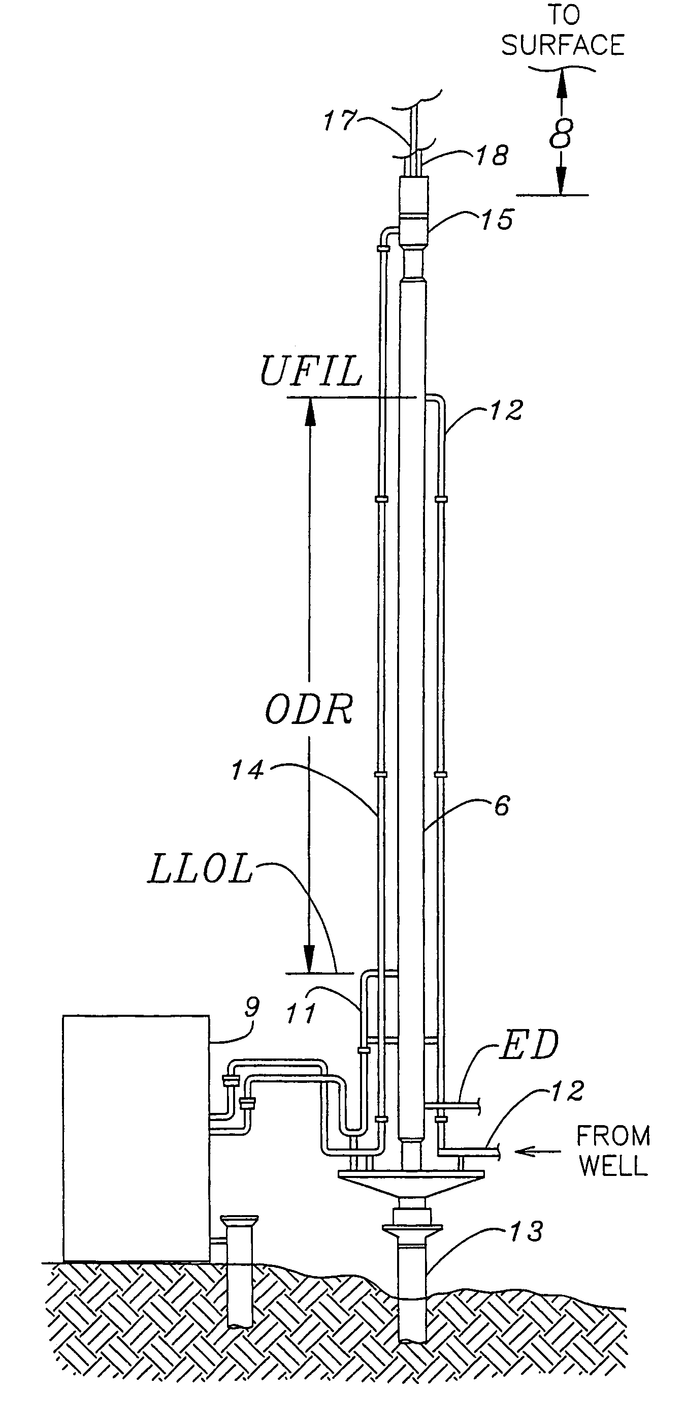
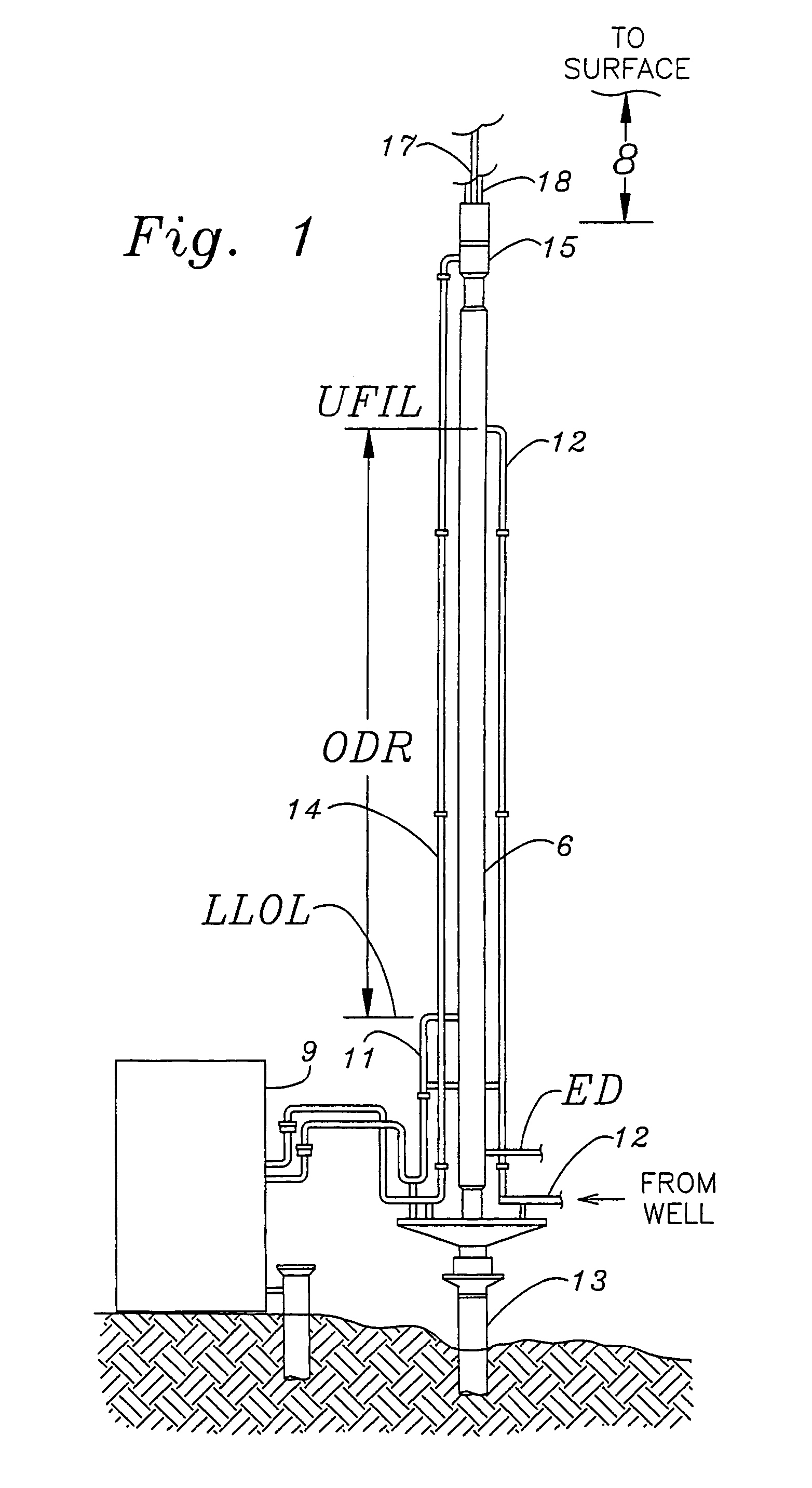
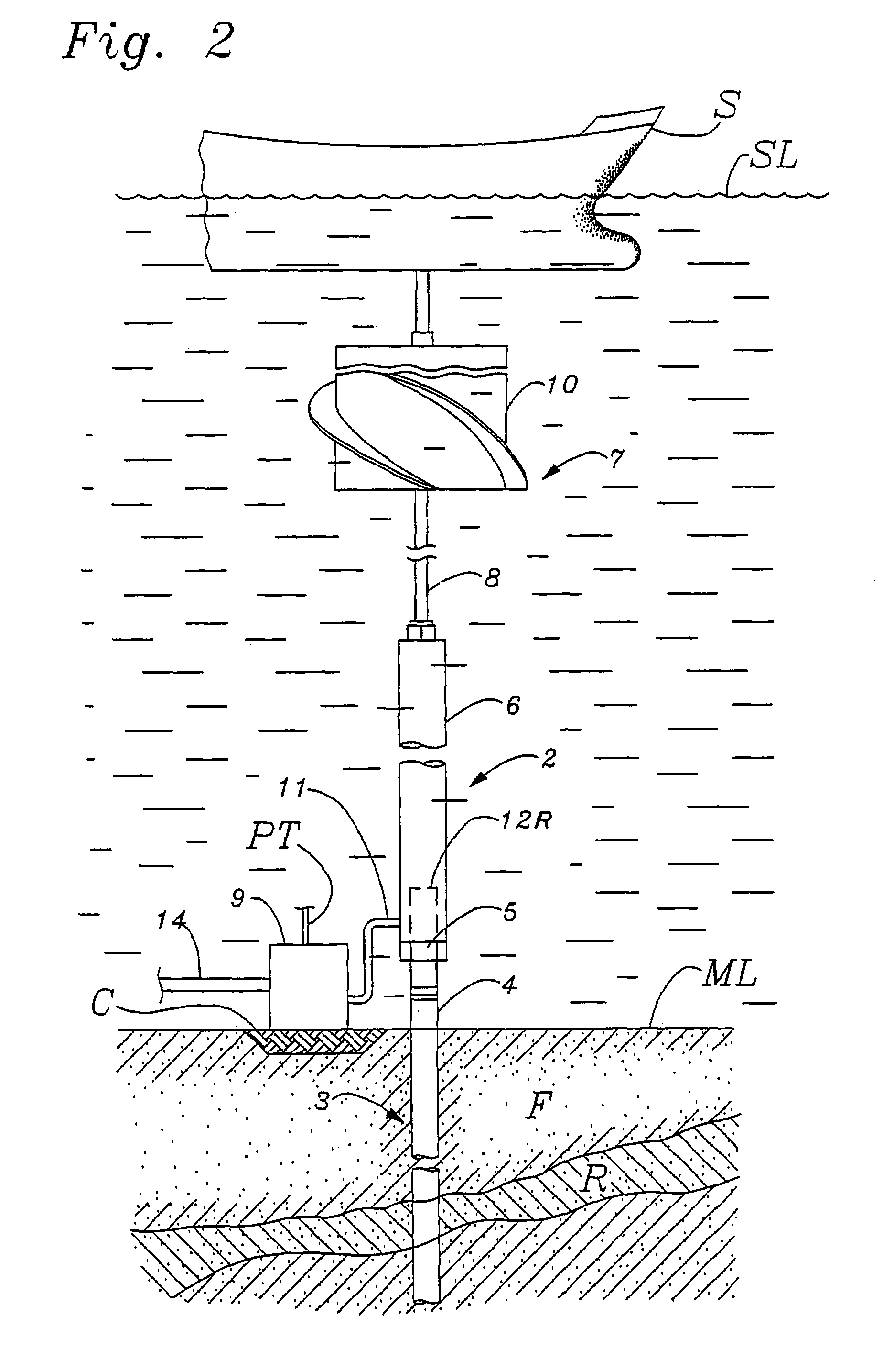
[0011]FIG. 1 shows a side view of a tubular vertical separator 6 supported by a piling 13 and a liquid or dense fluid pump assembly 9 similar to the comparable devices shown in FIG. 2. The preferred elongated tubular separator 6 in FIG. 1 is essentially composed of one or more pipe sections or other cylindrical elements having a nominal diameter larger than the nominal diameter of the concentric riser assembly 8 similar to that described for the elongated vertical separator 6 shown in FIG. 2. The tubular separator 6 shown in FIG. 1 comprises at least one multi-phase fluid inlet 12, at least one liquid or more-dense fluid outlet 11 connected to the pump assembly 9, and at least one vapor or less-dense-phase fluid outlet connected to a riser assembly 8.

[0012]The multi-phase fluid inlet line 12 is in fluid communication and is thus supplied by a subsea well (not shown in FIG. 1) or a manifold connected to a plurality of subsea wells. The pressurized outlet line 14 from the pump assembl...


PUM


Abstract

A preferred embodiment of the inventive fluid delivery system comprises a vertical liquid/vapor separator and riser assembly that comprises a multi-phase separator inlet, a vapor outlet and riser, and a liquid outlet port connected to a hydraulically-driven centrifugal pump. By controlling the operational speed of the pump, the level of the separated liquid within the separator can be controlled without the need for control valves. The vertical separator is capable of low pressure operation and large variations in controlled liquid levels within the separator, allowing the relatively slow reaction time pump to control the liquid level from low pressure wells penetrating low pressure reservoirs.

Description

CROSS REFERENCE TO RELATED APPLICATIONS [0001]This application is a continuation of U.S. patent application Ser. No. 10 / 138,020 filed in the United States Patent and Trademark Office on May 2, 2002 now U.S. Pat. No. 6,651,745.FIELD OF THE INVENTION[0002]This invention relates to offshore resource-recovery devices and processes. More specifically, the invention is concerned with improved oil and gas or other multi-phase fluid production from offshore subsea wells, especially from ultra-deep offshore wells.BACKGROUND OF THE INVENTION[0003]Some offshore resource recovery activities, e.g., withdrawal of hydrocarbon fluids from a subsurface reservoir through a well tubular and riser assembly to surface fluid delivery facilities, have previously been accomplished using an offshore platform. The offshore platform typically supports at least a portion of the riser and fluid delivery facilities and other equipment needed to process and recover resource fluids.[0004]For shallow water depth lo...

Claims


Application Information

Patent Timeline
IPC IPC(8): E21B29/12E21B43/01E21B43/36
CPCE21B43/01E21B43/36
Inventor LUSH, DAVIDENG, JONATHANUCOK, HIKMETHOPGOOD, DAVELANDECK, CHRISCARMON, KEN
Owner CHEVROU USA INC
Why Eureka
Try Eureka