Optical system, display optical system and image-taking optical system
a technology of optical system and optical system, applied in the field of optical system, display optical system and image-taking optical system, can solve the problems of long optical path length and large apparatus, and achieve the effect of easy magnification and favorable correction of aberrations
- Summary
- Abstract
- Description
- Claims
- Application Information
AI Technical Summary
Benefits of technology
Problems solved by technology
Method used
Image
Examples
numerical example 1
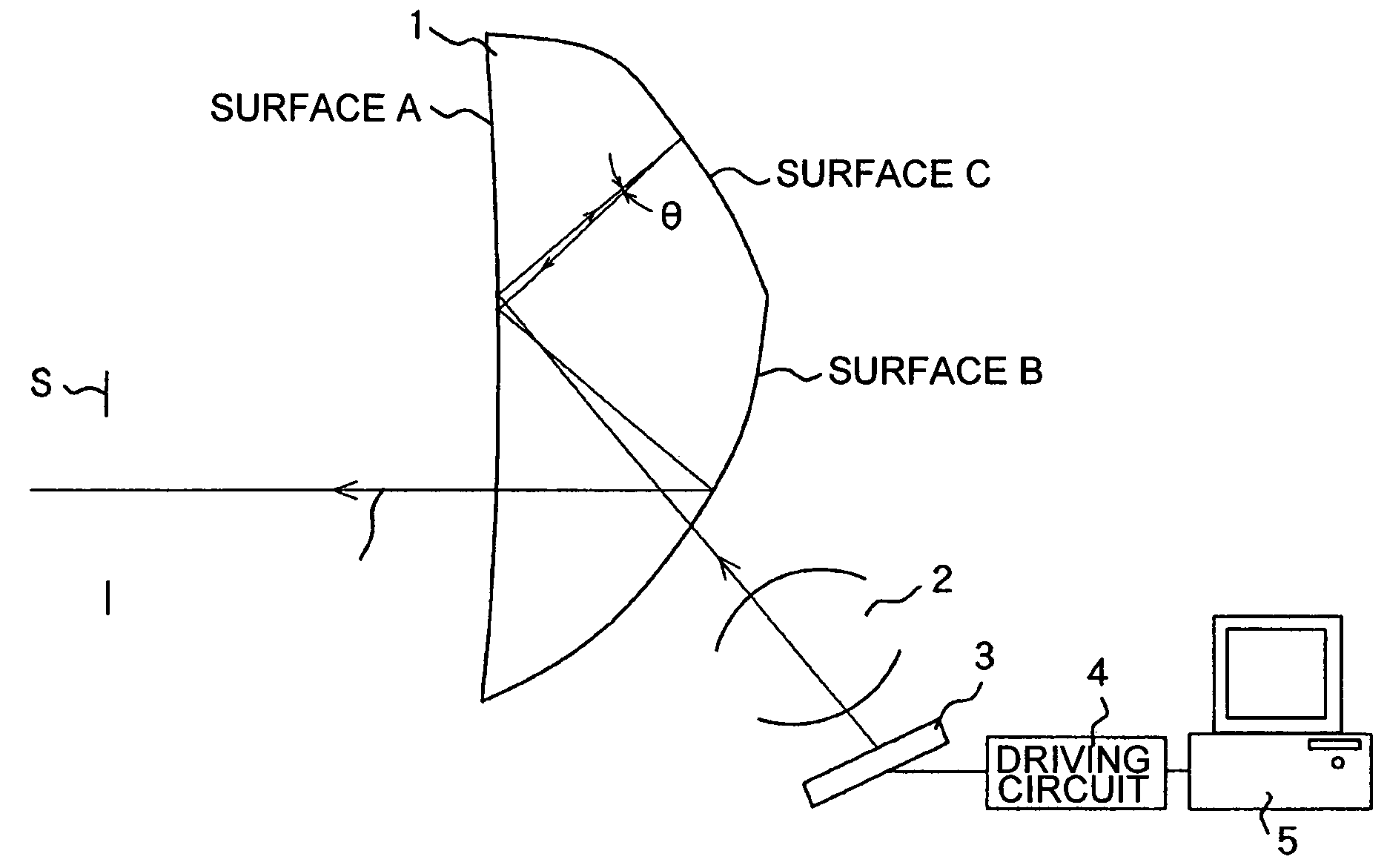
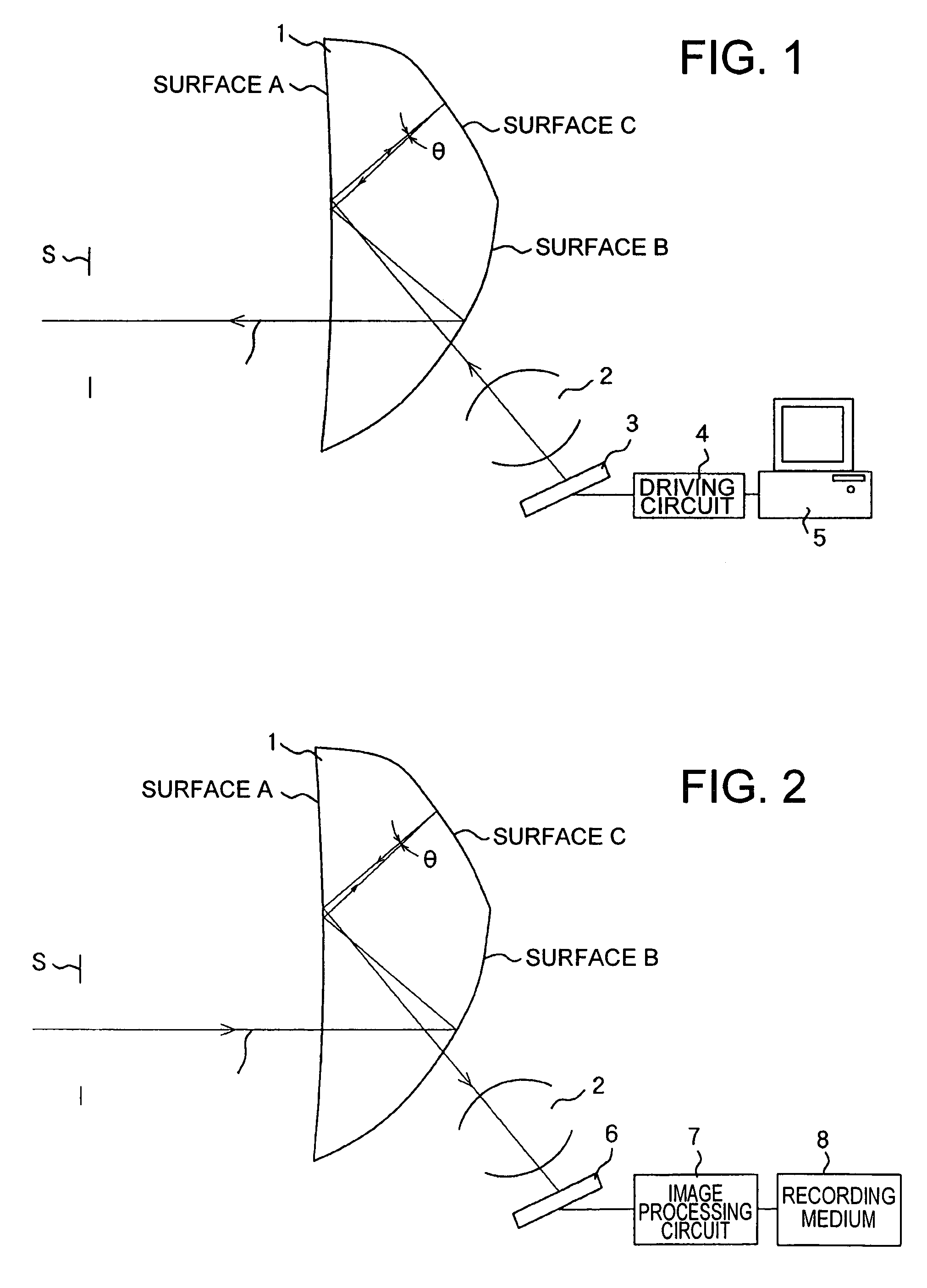
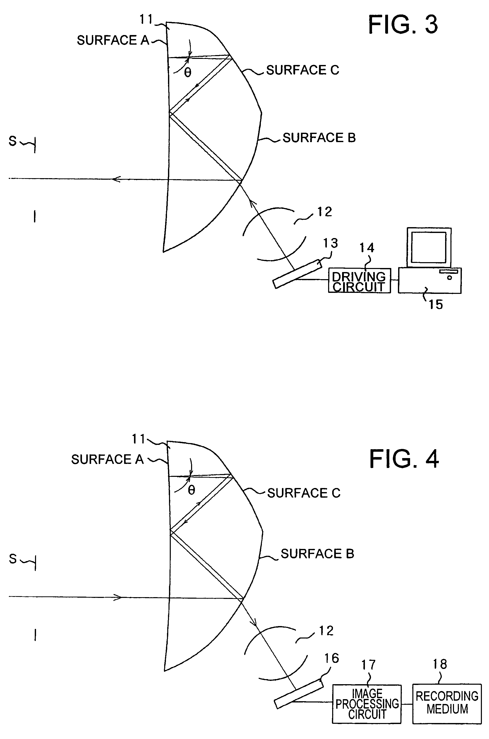
[0111]FIG. 5 is a cross-sectional view illustrating Numerical Example 1 of an optical system according to the present invention. This Numerical Example 1 corresponds to the above-described Embodiments 3 and 4. The optical element 11 is a prism-shaped transparent member, which is filled with an optical medium, and has three optical surfaces A to C, including a returning reflection surface (surface A).
[0112]S2, S4, S6 and S8 denote the same surface (surface A), and also S3 and S9 denote the same surface (surface B) Also S5 and S7 denote the same surface (surface C). S6 is the returning reflection surface, which has a returning reflection action, and S5 and S7 denote a DOE surface.
[0113]The second optical system 12 is made of the two optical elements 21 and 22, which respectively have two optical surfaces. The optical elements 21 and 22 are prism-shaped transparent members, which are filled with an optical medium.
[0114]All these surfaces are plane symmetric having the paper plane (yz-s...
numerical example 2
[0141]FIG. 6 is a cross-sectional view illustrating Numerical Example 2 of the present invention, and the optical data for this numerical example is shown in Table 2. This Numerical Example 2 corresponds to the above-described Embodiments 3 and 4. The optical element 11 is a prism-shaped transparent member, which is filled with an optical medium, and has three optical surfaces A to C, including a returning reflection surface (surface A).
[0142]S2, S4, S6 and S8 denote the same surface (surface A), and also S3 and S9 denote the same surface (surface B). Also S5 and S7 denote the same surface (surface C). S6 is the returning reflection surface, which has a returning reflection action.
[0143]The optical element 12 constituting the second optical system is made of a prism-shaped transparent member, which is filled with an optical medium, and has three optical surfaces S10, S11 and S12, including a diffractive optical surface (DOE surface) S10.
[0144]All these surfaces are plane symmetric h...
numerical example 3
[0150]FIG. 7 is a cross-sectional view illustrating Numerical Example 3 of the present invention, and the optical data for this numerical example is shown in Table 3. This Numerical Example 3 corresponds to the above-described Embodiments 3 and 4. The optical element 11 is a prism-shaped transparent member, which is filled with an optical medium, and has three optical surfaces A to C, including a returning reflection surface (surface A).
[0151]S2, S4, S6 and S8 denote the same surface (surface A), and also S3 and S9 denote the same surface (surface B) Also S5 and S7 denote the same surface (surface C). S6 is the returning reflection surface, which has a returning reflection action.
[0152]The optical element 12 constituting the second optical system is made of a prism-shaped transparent member, which is filled with an optical medium, and has three optical surfaces S10, S11 and S12, including a diffractive optical surface (DOE surface) S11.
[0153]All these surfaces are plane symmetric ha...
PUM
 Abstract
Description
Claims
Application Information
 - R&D
- Intellectual Property
- Life Sciences
- Materials
- Tech Scout
- Unparalleled Data Quality
- Higher Quality Content
- 60% Fewer Hallucinations
Browse by: Latest US Patents, China's latest patents, Technical Efficacy Thesaurus, Application Domain, Technology Topic, Popular Technical Reports.
© 2025 PatSnap. All rights reserved.Legal|Privacy policy|Modern Slavery Act Transparency Statement|Sitemap|About US| Contact US: help@patsnap.com


