Wristwatch and band timepiece

a wristwatch and band technology, applied in the field of wristwatch band and wristwatch, can solve the problems of reducing the reliability of attaching and holding the band to the case band with a predetermined strength, affecting use feeling, and not desirable techniques of patent document 1, and achieves the effect of convenient attachment and removal and sufficient attachment strength

Inactive Publication Date: 2007-05-01
SEIKO INSTR INC
View PDF5 Cites 13 Cited by
  • Summary
  • Abstract
  • Description
  • Claims
  • Application Information

AI Technical Summary

Benefits of technology

[0012]An object of the present invention exists in providing a wristwatch in which the band can be easily attached to and detached from the case band without using the exclusive tool, in which a sufficient attachment strength with respect to the case band can be ensured, and moreover whose use feeling is good, and a band for timepiece, which is possessed in this wristwatch.
[0018]In the mode of this invention, by manually rotating the tubular rotation body, since the one pair of coupling axles can be simultaneously moved in mutually reverse directions to thereby be protruded and immersed with respect to the end face of the case band connection end part in its width direction, it is possible to more improve the attachment / detachment operability of the band with respect to the case band.
[0024]In the mode of this invention, since the tubular rotation body facing the operation opening is concealed at a use time of the wristwatch, an appearance at the use time is good, and there is no fear that the tubular rotation body is unguardedly rotated by the fact that other object contacts with this tubular rotation body at the use time.
[0030]In the mode of this invention, by manually rotating the tubular rotation body, since the one pair of coupling axles can be simultaneously moved in mutually reverse directions to thereby be protruded and immersed with respect to the end face of the case band connection end part in its width direction, it is possible to more improve the attachment / detachment operability of the band with respect to the case band.
[0036]In the mode of this invention, since the tubular rotation body facing on the operation opening is concealed at the use time of the wristwatch, the appearance at the use time is good, and there is no fear that the tubular rotation body is unguardedly rotated by the fact that other object contacts with this tubular rotation body at the use time.

Problems solved by technology

Reversely to this, in a case where the spring property of the spring bar is weak, there decreases a reliability for attaching and holding the band to the case band with a predetermined strength.
For this reason, in ensuring both of an easy attachment / detachment operability of the band with respect to the case band and a sufficient attachment strength, the technique of the Patent Document 1 is not desirable.
Further, there is considered the fact that the handle of the spring bar existing along a back side of the band contacts with a user's wrist during use and, in this case, there is the fact that a use feeling is impaired.
Therefore, a work for attaching the band to the case band is comparatively troublesome as well.

Method used


Image

  • Wristwatch and band timepiece
  • Wristwatch and band timepiece
  • Wristwatch and band timepiece

Examples


Embodiment Construction

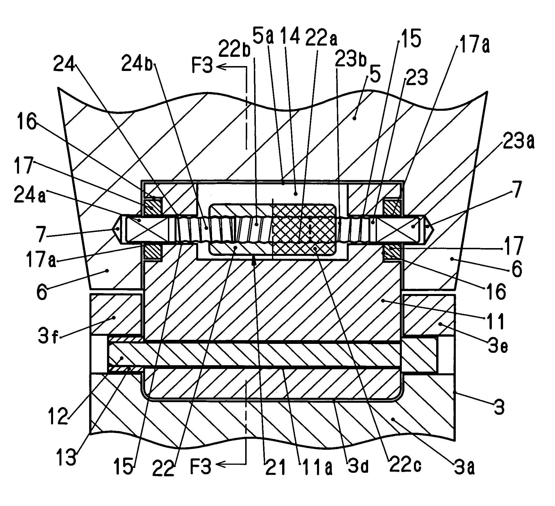
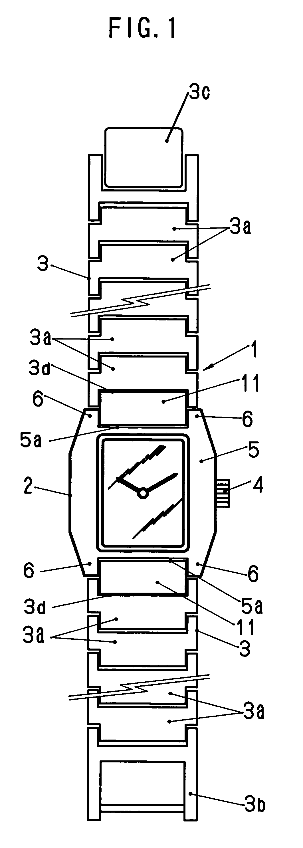
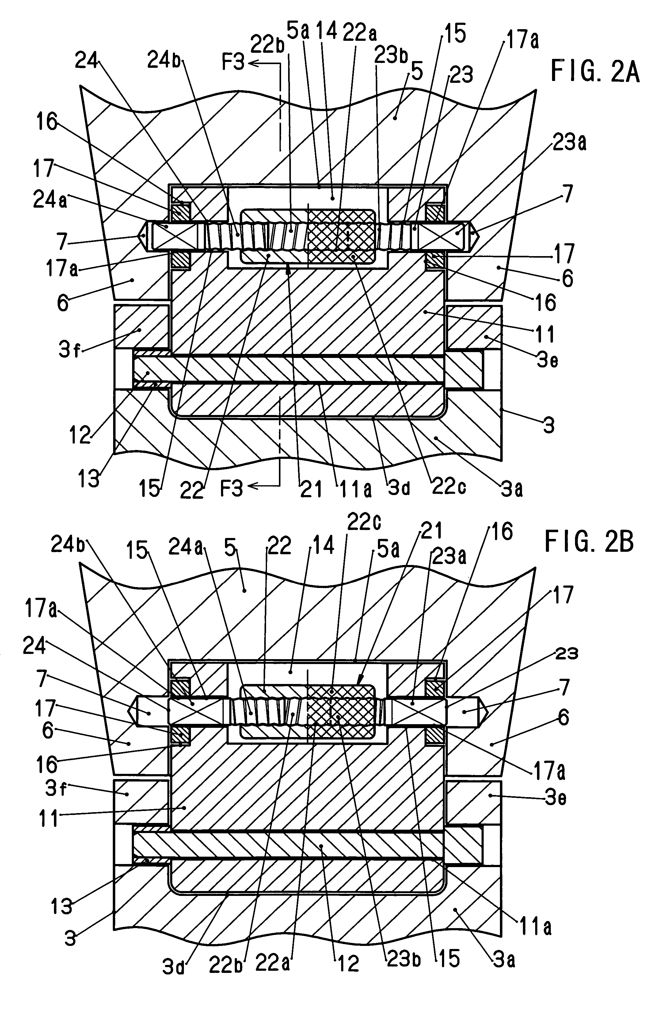
[0047]A 1st embodiment of the present invention is explained by referring to FIG. 1 to FIG. 4.

[0048]In a wristwatch 1 shown in FIG. 1, one pair of bands 3 for instance are attached to a timepiece armor assembly 2. Within the timepiece armor assembly 2, there are accommodated a dial, a timepiece movement not shown in the drawing, and the like. Incidentally, in FIG. 1, a reference numeral 4 denotes a crown.

[0049]As shown in FIG. 1, the bands 3 are detachably attached to a case band 5, made of a metal or a synthetic resin, that the timepiece armor assembly 2 possesses, while corresponding to 6 o'clock and 12 o'clock sides of the dial. The band 3 is formed by rotatably coupling plural coupling band pieces 3a made of the metal or the synthetic resin by bar-like piece-coupling components (not shown in the drawing) with this piece-coupling component being made a center. A connection end part 3b that one band 3 has and a connection end part 3c that the other band 3 has are capable of engagi...


PUM


Abstract

To provide a wristwatch in which a band can be easily attached to and detached from a case band without using an exclusive tool, in which a sufficient attachment strength with respect to the case band can be ensured, and moreover whose use feeling is good. Bow feet each of which has an attachment hole are protrusively provided in a case band, and a bow crotch receiving an end piece (case band connection end part) of a band capable of being attached to and detached from the case band so as to be capable of being put in and taken out is formed between the bow feet. An operation opening is provided in the end piece. A coupler having possessed a tubular rotation body and coupling axles is internally mounted in the end piece. The tubular rotation body has female screws, and the coupling axles are meshed with these female screws. The tubular rotation body is provided while facing on the operation opening, and manual-rotation-operated from an outside of the end piece. The coupling axles are locked to the end piece, and provided so as to be capable of being protruded and immersed with respect to an end face of the end piece in its width direction in accordance with the rotation of the tubular rotation body. The coupling axles having been protruded and immersed are inserted into and withdrawn from the attachment holes, so that an attachment / detachment of the band with respect to the case band is made possible.

Description

BACKGROUND OF THE INVENTION[0001]1. Field of the Invention[0002]The present invention relates to a band for timepiece and a wristwatch in which this band has been detachably attached to a case band.[0003]2. Description of the Prior Art[0004]Hitherto, there is known a technique detachably attaching the band to the case band of the wristwatch without using an exclusive tool (for example, refer to Patent Document 1).[0005]In this technique of the Patent Document 1, a metal plate having two curl parts is attached to an end part of a leather band, and a spring bar is provided while extending over the two curl parts. The spring bar has a handle being bent approximately like the V letter in an intermediate part of a spring wire material, and one end and the other end, which are bent so as to become mutually remote from this handle. Both ends of this spring bar are individually inserted into the two curl parts and rotatably held, and the handle is disposed between the two curl parts. And, i...

Claims


Application Information

Patent Timeline
Patent Type & Authority Patents(United States)
IPC IPC(8): G04B19/00A44C5/14A45C11/10
CPCG04B37/1486A44C5/14G04B37/1493
Inventor HIRANUMA, HARUKIOMORI, NOBUKAZU
Owner SEIKO INSTR INC
Why Eureka
Try Eureka