Inertial measurement unit using rotatable MEMS sensors

a technology of inertial measurement and sensor, applied in the direction of linear/angular speed measurement, instruments, surveying and navigation, etc., can solve the problems of inability to directly determine, inertial calculation based on the measurement of the sensor's output operating under dynamic conditions, and can contain alternately positive and negative errors, so as to improve the sense accuracy

Inactive Publication Date: 2007-05-01
NAT TECH & ENG SOLUTIONS OF SANDIA LLC
View PDF22 Cites 29 Cited by
  • Summary
  • Abstract
  • Description
  • Claims
  • Application Information

AI Technical Summary

Benefits of technology

[0012]Under static operating conditions, where the body to which the sensor is attached is not in motion, sensor output can be measured in a multiple of sensor positions, for example, an initial position and a position where the integral MEM stage is rotated by 180 degrees from the initial position. A comparison of the sensor output at the initial position and the output of the sensor at a rotated position allows for a determination of the bias error in the sensor's output. Bias error determination can be accomplished by sum-differencing computations based on a sensor's output in the initial and rotated positions. The bias error can then be accounted for in subsequent inertial calculations, for example, during dynamic operation of the sensor where the body to which the sensor is attached is moving, providing an improved sense accuracy for the MEM inertial sensor of the present invention.
[0013]The foregoing discussion concerns the use of a rotation capability of a MEM inertial sensor to determine a sensor's bias under a static operating condition of the sensor. Under a dynamic operating condition of the sensor, where the body to which the sensor is attached is moving, it may not be possible to directly determine the bias error because the bias error can be obscured by a dynamic input to the sensor (i.e. a sensed acceleration or rotation rate). However, the present invention additionally provides a method for bias error compensation of a sensor under a dynamic operating condition. While a MEM inertial sensor is operated under dynamic conditions, measurements of a sensor's output are taken at multiple rotational positions (for example at 0 degrees and 180 degrees) repeatedly over time, while the sensor is under dynamic operating conditions. For a sensor under a dynamic operating condition, the measurement of the sensor's output in the initial and the rotated positions can alternately contain positive and negative contributions due to the bias of the sensor. Inertial calculations based on the measurements of the sensor's output operating under dynamic conditions, can therefore also contain alternately positive and negative errors, due to the alternately positive and negative contributions of the sensor's bias, to the measured output of the sensor. Under a dynamic operating condition, errors in the inertial calculations due to alternately positive and negative contributions from the bias in a sensor's measured outputs are accumulated over time, and tend to average out, thus mitigating their aggregate effect providing an improved sense accuracy for a MEM inertial sensor of the present invention, under dynamic operating conditions.
[0017]Where the example IMU is undergoing static or dynamic operating conditions, measurements of the outputs of any three of the MEM sensors is sufficient to allow inertial calculations to be performed, continuously over time, for a body to which the IMU may be attached, while the fourth sensor can be rotatably transitioning from a first position to a second, rotated position. Once a sensor has completed transitioning between positions, it's output is measured and utilized in subsequent inertial calculations. In this example embodiment, at any given time, measurements of the outputs of three sensors are used in inertial calculations while a fourth sensor is undergoing a rotational transition. Once a sensor has completed a rotational transition, a new sensor is selected for rotation and the outputs of the remaining three sensors are measured. Sequentially selecting a different sensor for rotation while using the measured outputs of the remaining three non-rotating sensors for performing inertial calculations, allows the inertial calculations to be performed continuously through time. This embodiment of the present invention provides that the effects due to bias error in the inertial calculations are mitigated over time, by the accumulation in the inertial calculations of both positive and negative effects of bias error arising from alternately measuring each sensors output, in positions rotated 180 degrees apart. An embodiment of the present invention, an IMU comprising a plurality of MEM inertial sensors with integral rotational means, provides an IMU having improved sense accuracy under both static or dynamic operating conditions.

Problems solved by technology

Under a dynamic operating condition of the sensor, where the body to which the sensor is attached is moving, it may not be possible to directly determine the bias error because the bias error can be obscured by a dynamic input to the sensor (i.e. a sensed acceleration or rotation rate).
Inertial calculations based on the measurements of the sensor's output operating under dynamic conditions, can therefore also contain alternately positive and negative errors, due to the alternately positive and negative contributions of the sensor's bias, to the measured output of the sensor.

Method used


Image

  • Inertial measurement unit using rotatable MEMS sensors
  • Inertial measurement unit using rotatable MEMS sensors
  • Inertial measurement unit using rotatable MEMS sensors

Examples


first embodiment

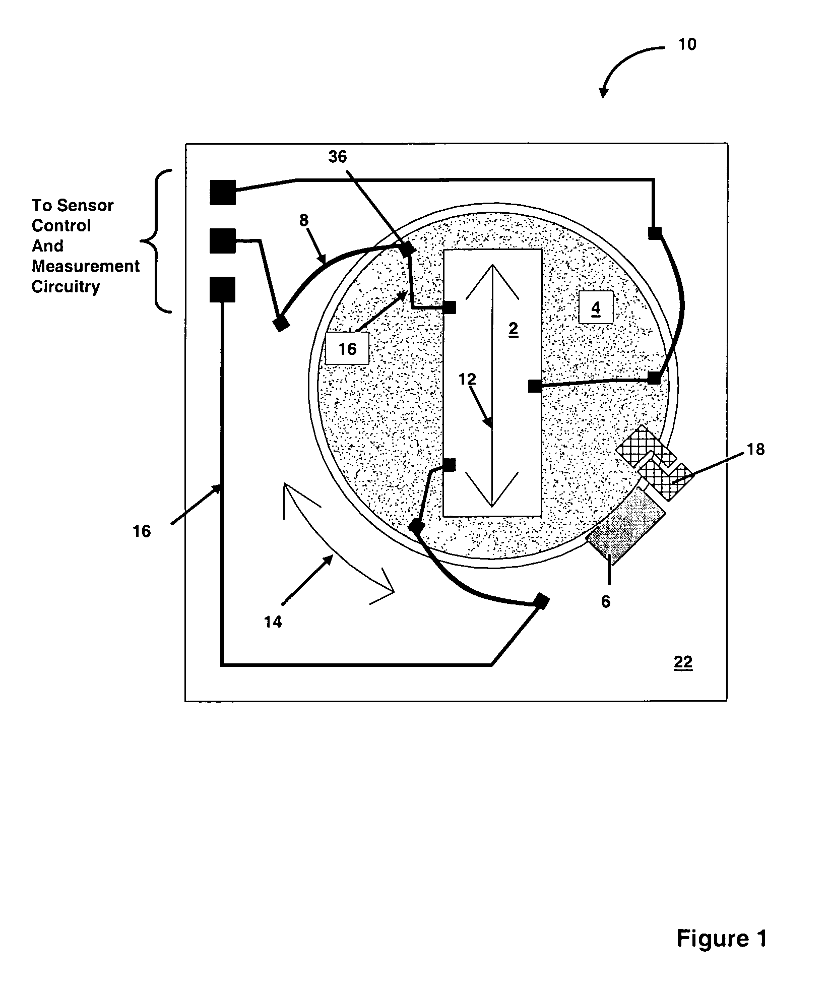
[0029]FIG. 1 is a schematic plan view of a MEM inertial sensor 10 according to the present invention. The micromechanical inertial sensor 10, comprises a base 22 providing mechanical support for a rotatable micromechanical stage 4. A MEM inertial sensing element 2, having an inertial sense axis 12 is disposed on stage 4. An actuator 6 is operatively coupled to micromechanical stage 4, and rotates stage 4 about a rotational axis that is substantially perpendicular to sense axis 12 of sense element 2 (i.e. about an axis extending out of the plane of FIG. 1) and in the rotational direction as indicated by the arc 14.

[0030]Actuator 6 for rotating the stage 4 may further include mechanical stops 18, or indexing gears, latches or the like for orienting and positioning stage 4, at known rotational positions. Actuator 6 for rotating micromechanical stage 4 can comprise an electrostatic actuator, an electromagnetic actuator, a shape memory alloy actuator, a phase change based actuator, a pie...

second embodiment

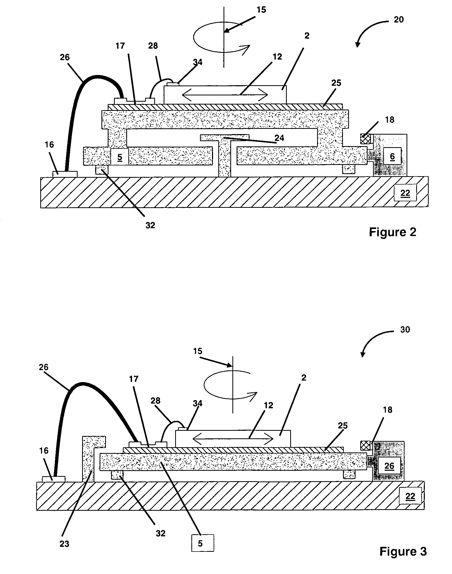
[0034]FIG. 2 shows a schematic cross section view of a MEM inertial sensor 20 with integral rotational means according to the present invention. The MEM inertial sensor 20 comprises a base 22 providing mechanical support for a rotatable micromechanical stage 5. Stage 5 can be fabricated using LIGA technologies. A MEM inertial sensing element 2, having an inertial sense axis 12 is disposed on stage 5. Stage 5 is rotatably affixed to base 22 by a hub 24. An actuator 6 is operatively coupled to micromechanical stage 5, and rotates stage 5 about a rotational axis 15 which is substantially perpendicular to the sense axis 12 of the sense element 2. Actuator 6 for rotating micromechanical stage 5 can comprise an electrostatic actuator, an electromagnetic actuator, a shape memory alloy actuator, a phase change based actuator, a piezoelectric actuator or a thermal actuator. The actuator 6 can be mechanically coupled to rotate stage 5 through gears, ratchets, indexing pawls, etc. Actuator 6 f...

third embodiment

[0038]FIG. 3 shows a schematic cross section view of a MEM inertial sensor 30 with integral rotational means according to the present invention. The MEM inertial sensor 30 comprises a base 22 providing mechanical support for a rotatable micromechanical stage 5. Stage 5 can be fabricated using LIGA technologies. A MEM inertial sensing element 2, having an inertial sense axis 12 is disposed on stage 5. Stage 5 is rotatably constrained to base 22 by restraining clips 23, that slideably engage stage 5. Restraining clips 23 are attached to base 22 and are spaced about the perimeter of stage 5 (e.g. typically at three locations). An actuator 6 is operatively coupled to micromechanical stage 5, and rotates stage 5 about a rotational axis 15 which is substantially perpendicular to the sense axis 12 of the sense element 2. Actuator 6 for rotating micromechanical stage 5 can comprise an electrostatic actuator, an electromagnetic actuator, a shape memory alloy actuator, a phase change based ac...


PUM


Abstract

A MEM inertial sensor (e.g. accelerometer, gyroscope) having integral rotational means for providing static and dynamic bias compensation is disclosed. A bias compensated MEM inertial sensor is described comprising a MEM inertial sense element disposed on a rotatable MEM stage. A MEM actuator drives the rotation of the stage between at least two predetermined rotational positions. Measuring and comparing the output of the MEM inertial sensor in the at least two rotational positions allows for both static and dynamic bias compensation in inertial calculations based on the sensor's output. An inertial measurement unit (IMU) comprising a plurality of independently rotatable MEM inertial sensors and methods for making bias compensated inertial measurements are disclosed.

Description

CROSS REFERENCE TO RELATED APPLICATIONS[0001]This application is a divisional application of, and claims priority under 35 U.S.C. 121 to, U.S. application Ser. No. 10 / 932,957 Titled “Inertial Measurement Unit Using Rotatable MEMS Sensors”, filed on Sep. 2, 2004 now U.S. Pat. No. 7,066,004. The entirety of the contents of U.S. application Ser. No. 10 / 932,957 is incorporated herein by reference.STATEMENT REGARDING FEDERALLY SPONSORED RESEARCH OR DEVELOPMENT[0002]The United States Government has certain rights in this invention pursuant to Department of Energy Contract No. DE-AC04-94AL85000 with Sandia Corporation.FIELD OF THE INVENTION[0003]The present invention relates to micromechanical and microelectromechanical (MEM) inertial sensors. The invention further relates to bias error compensation of MEM inertial sensors by providing integral rotational means. The invention also relates to Inertial Measurement Units (IMUs) comprised of MEM inertial sensors having integral rotational mean...

Claims


Application Information

Patent Timeline
Patent Type & Authority Patents(United States)
IPC IPC(8): G01P3/00G01P21/00
CPCG01C19/5719G01P1/00G01P21/00
Inventor KOHLER, STEWART M.ALLEN, JAMES J.
Owner NAT TECH & ENG SOLUTIONS OF SANDIA LLC
Why Eureka
Try Eureka