Bracket for supporting structural element to support structure

Inactive Publication Date: 2007-05-08
PEIKKO GROUP
View PDF39 Cites 14 Cited by
  • Summary
  • Abstract
  • Description
  • Claims
  • Application Information

AI Technical Summary

Benefits of technology

[0007]An underlying idea of the invention is that the bracket part is movably arranged to the first support part to be cast into the concrete pile. This enables the bracket part to be moved with regard to the concrete pile at the construction site when one end of the concrete beam is mounted onto the bracket part, thereby enabling errors, if any, in casting and in the position of the concrete pile to be corrected at the construction site.
[0008]An advantage of the bracket of the invention is that greater precision is achieved in the mounting of a construction unit with regard to the concrete pile.
[0009]Since the inner diameter of the through-holes in the bracket part is greater

Problems solved by technology

A problem with some known brackets is that they do not comprise a proper arrangement to allow for other adjustments than those made in the longitudinal direction of the beam.
As a result, errors in casting, for example, cannot be corrected.
A concrete pile is usually provided with a first support part that is cast at least

Method used


Image

  • Bracket for supporting structural element to support structure
  • Bracket for supporting structural element to support structure
  • Bracket for supporting structural element to support structure

Examples


Embodiment Construction

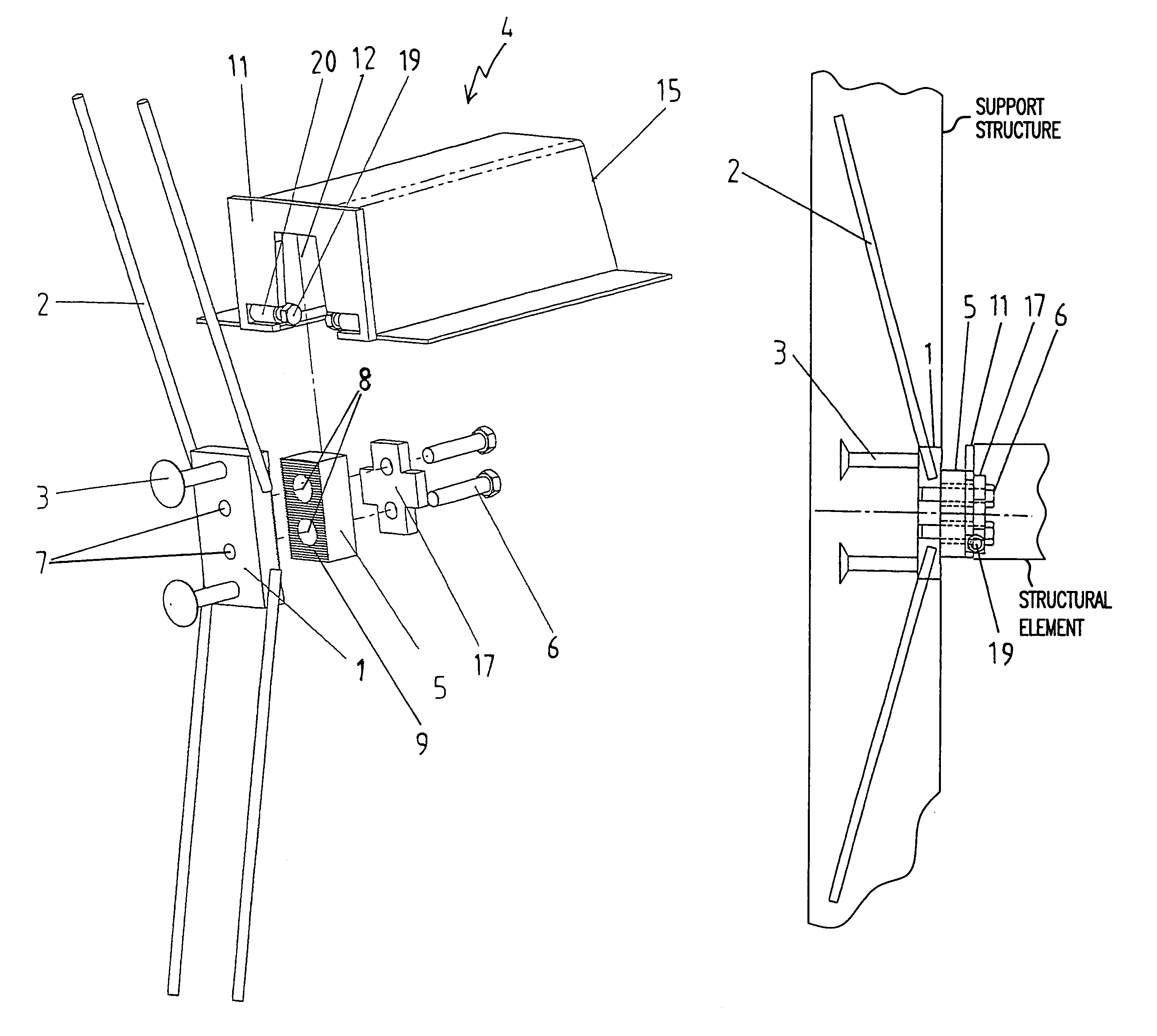
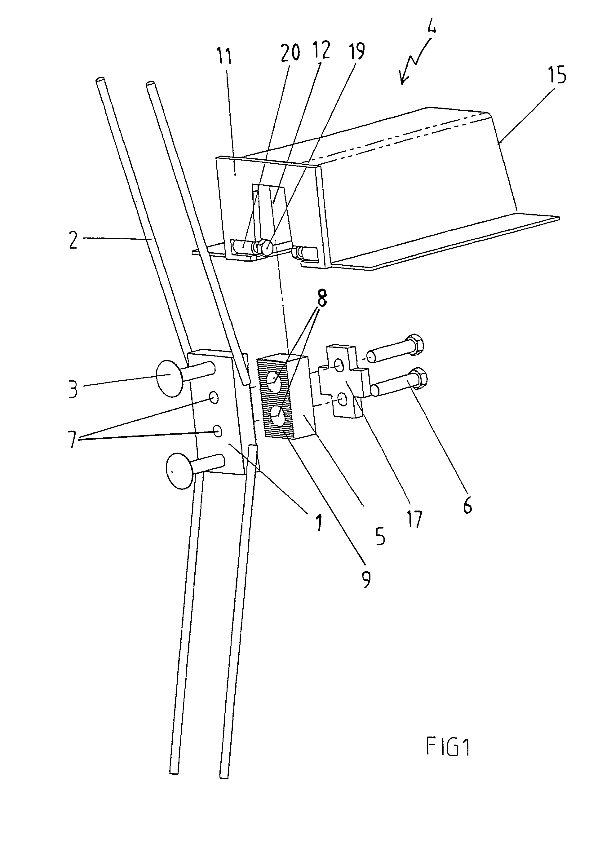
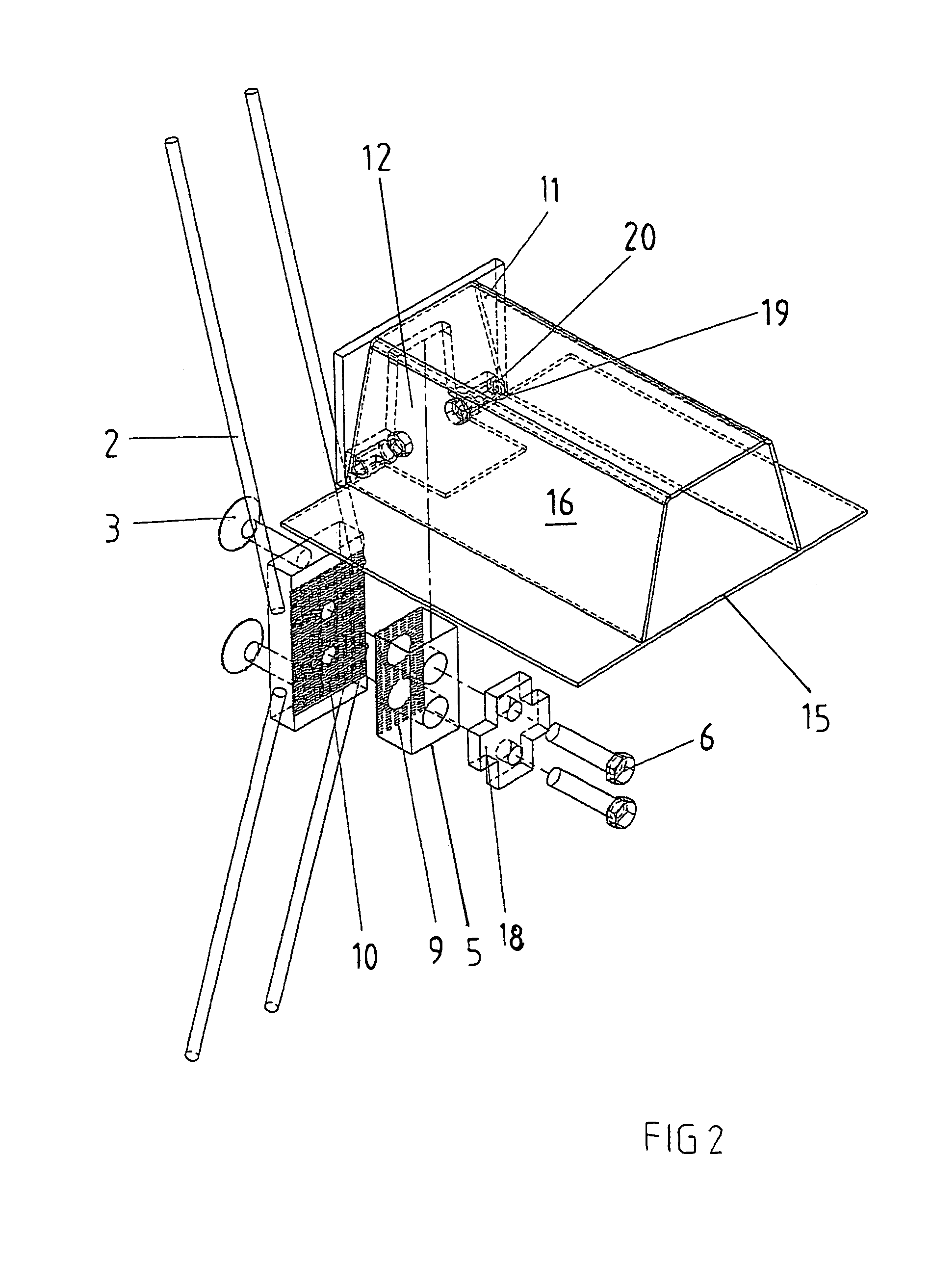
[0020]The Figures show a bracket for supporting a structural element, such as a concrete beam, on a support structure in a building. The structural element may also be made of some other material than concrete, such as steel.

[0021]The bracket comprises a first support part 1 which is meant to be cast at least partly into the support structure as shown in FIG. 3. In the Figures the first support part 1 is a rectangular plate part.

[0022]The first support part 1 shown in the Figures is provided with bonds 2 and 3 fastened thereto for anchoring the first support part 1 to the support structure. In the Figures the bonds are deformed steel bars 2 and headed pins 3. The deformed steel bars 2 are arranged in a slanting position such that the continuations (not shown) of the centre lines of the deformed steel bars 2 intersect outside the support structure. This preferred positioning of the deformed steel bars 2 allows the strain caused by the eccentricity of shear force to be reduced.

[0023]T...


PUM


Abstract

A bracket for supporting a structural element, such as a precast concrete beam, on a concrete pile or similar support structure in a building includes a first support part (1) which is cast at least partly into the concrete pile. The first support part (1) includes a bracket part (5) for supporting the structural element so that the structural element bears against the concrete pile. The bracket part (5) is movably fastened to the first support part (1), which is cast at least partly into the concrete pile, such that the position of the bracket part (5) with regard to the concrete pile can be changed.

Description

FIELD OF THE INVENTION[0001]The invention relates to a bracket for supporting a structural element, such as a precast concrete beam, on a concrete pile or a similar support structure of a building, the bracket comprising a first support part which is cast at least partly into the concrete pile, the first support part comprising a bracket part for supporting the structural element so that the structural element bears against the concrete pile, the first support part comprising threaded holes for bolts and the bracket part comprising through-holes through which the bolts are driven, the bracket part being movably fastened with the bolts to the first support part, which is cast at least partly into the concrete pile, such that the position of the bracket part with regard to the concrete pile can be changed.[0002]A problem with some known brackets is that they do not comprise a proper arrangement to allow for other adjustments than those made in the longitudinal direction of the beam. A...

Claims


Application Information

Patent Timeline
IPC IPC(8): E04B1/21E04B1/38E02D27/12E04B1/41E04B1/58
CPCE04B1/4121E04B1/21
Inventor PULKKANEN, JUHAHAYRINEN, PEKKALEINONEN, TARUVARVIKKO, KIMMOTUOMINEN, KARIKINNUNEN, JORMA
Owner PEIKKO GROUP
Why Eureka
Try Eureka