Power generation device utilizing river flow or seawater

a technology of power generation device and river flow, applied in the direction of machines/engines, endless-chain machines, mechanical equipment, etc., to achieve the effect of smooth circle around the sprocket and little meshing resistan

Active Publication Date: 2007-05-08
TAKEUCHI SEISAKUSHOKK
View PDF13 Cites 16 Cited by
  • Summary
  • Abstract
  • Description
  • Claims
  • Application Information

AI Technical Summary

Benefits of technology

[0010]During such operations, the river flowing water or the sea flowing water which has flowed into the openings of the buckets lined up at predetermined intervals on the outer surface of the lower portion of the conveyor and facing in the direction opposite to the direction in which the river flowing water or the sea flowing water advances can be kept circulated with the circulating portion of the conveyor over a long distance in the direction of the advance of the river flowing water or the sea flowing water along the outer surface of the lower circulating portion of the conveyor which extends in the substantially horizontal direction with the water left in a bucket-residing state without causing the water to leak from the buckets to the outside thereof. The greater part of the kinetic energy (impact force) of the river flowing water or sea flowing water which has flowed into the interior of the buckets can be kept transmitted to the circulating portion of the conveyor, to which the buckets are fixed, for a long period of time via the same buckets. The greater part of the kinetic energy of the river flowing water or the sea flowing water flowed into the buckets can be converted effectively into the conveyor circulating energy. As a result, the greater part of the kinetic energy of the river flowing water or the sea flowing water flowed into the buckets can be utilized effectively without waste as the energy for rotating the generator connected to one of the rotary shafts rotated in accordance with the circulation of the conveyor.
[0023]In such a case, the conveyor formed by a combination of a chain and sprockets can be circulated reliably in a substantially vertical plane without causing the conveyor to be slipped, by the river flowing water or sea flowing water working as a lubricant. In accordance with the circulation of the chain, the generator connected to one of the rotary shafts of the sprockets can be rotated reliably in the circulating direction of the chain. During this time, the chain can be circulated around the sprockets smoothly with little meshing resistance by using the river flowing water or sea flowing water working as a lubricant.

Problems solved by technology

However, none of the related art water wheel-utilizing generating sets adapted to rotate a generator by utilizing the energy of river flowing water or sea flowing water has a structure capable of effectively extracting the energy from the river flowing water or the sea flowing water, and such generating sets have not yet been developed to such a level that the generating sets satisfactorily meet the demand for electric power in the modern society in which a large quantity of electric power is consumed.

Method used


Image

  • Power generation device utilizing river flow or seawater
  • Power generation device utilizing river flow or seawater
  • Power generation device utilizing river flow or seawater

Examples


Embodiment Construction

[0030]A best mode for carrying out the invention will now be described with reference to the drawings.

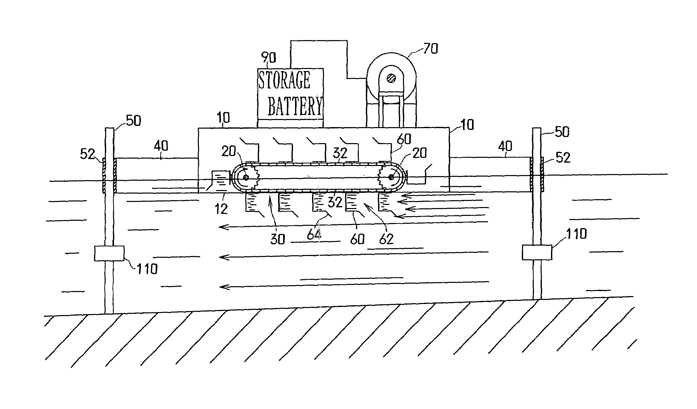
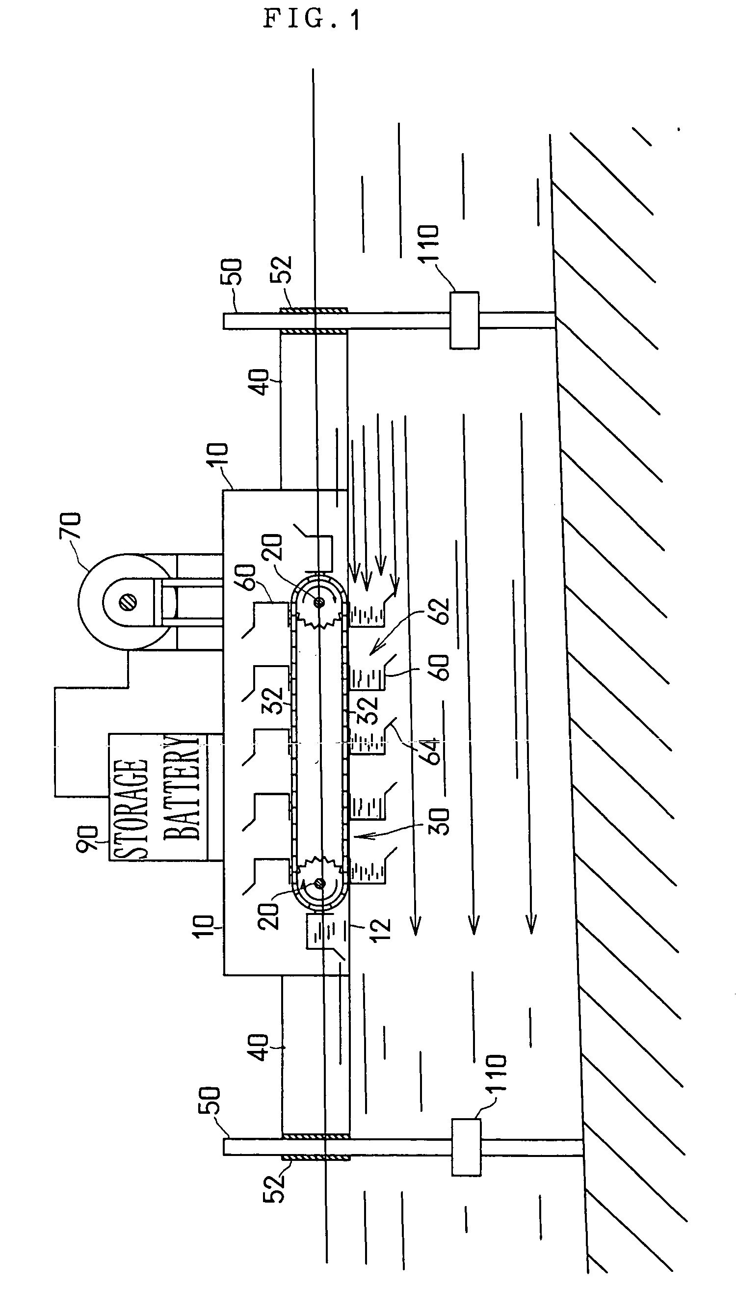
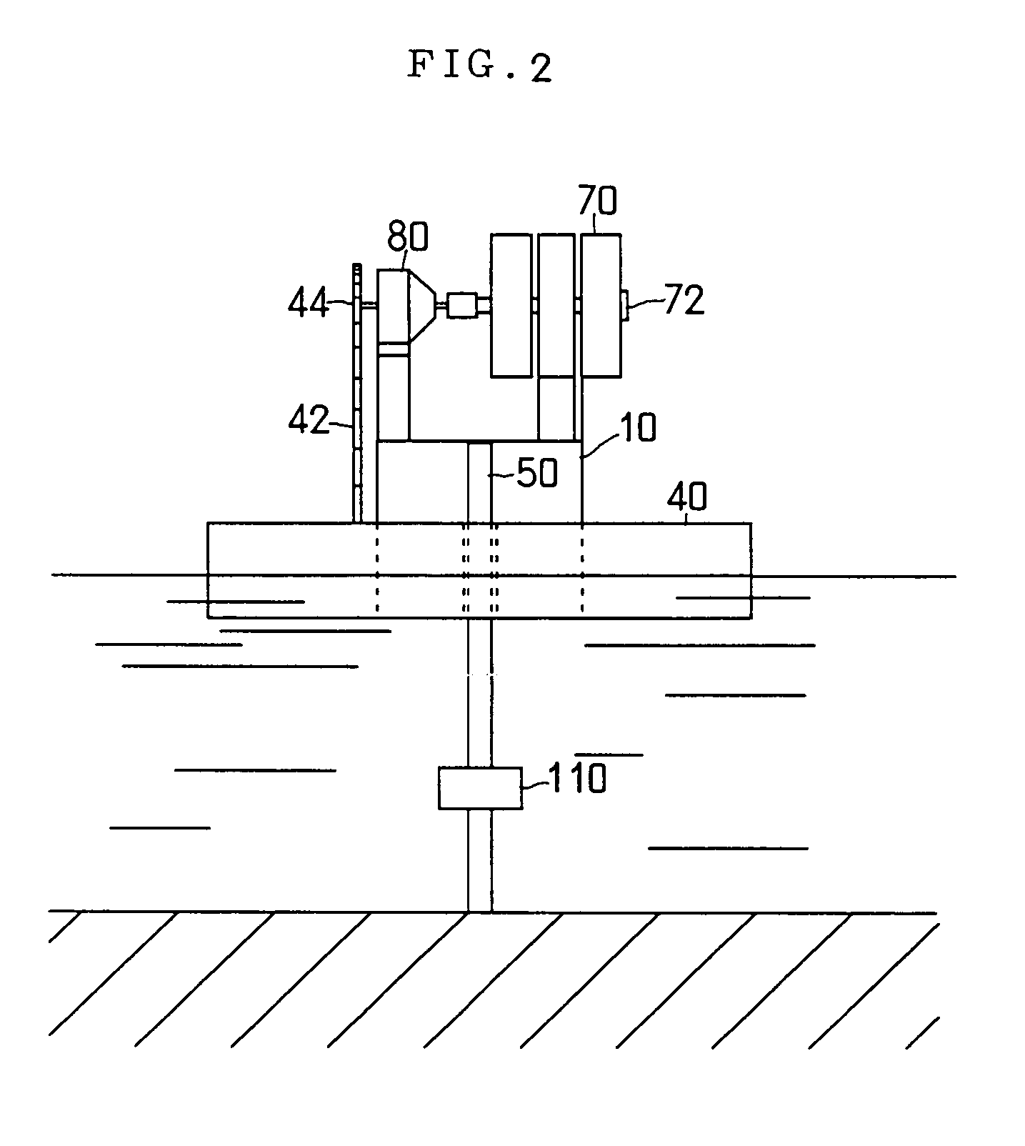
[0031]FIG. 1 and FIG. 2 show a preferred mode of embodiment of the generating set utilizing mainly river flowing water according to the present invention, and FIG. 3 and FIG. 4 a preferred mode of embodiment of the generating set utilizing mainly sea flowing water according to the present invention.

[0032]As shown in FIG. 1 or FIG. 3, these generating sets are provided with a pair of rotary shafts 20 in front and rear portions of the interior of a substantially rectangular longitudinally elongated frame 10 a lower end of which is opened widely, in such a manner that the two rotary shafts are arranged rotatably so as to extend across the interior of the frame 10. Around the front and rear rotary shafts 20 in the interior of the frame 10, a longitudinally longer conveyor 30 is supported so that circulating portions 32 thereof are turned substantially horizontally in the shape of a loop...


PUM


Abstract

A conveyor (30) having a plurality of buckets (60) lined up in and fixed to an inner side of a frame (10) is supported so that the conveyor can be circulated in the shape of a loop and substantially horizontally in a substantially vertical plane via rotary shafts (20). The frame (10) is supported so that the frame can be slidingly moved in the vertical direction around guide rods (50) stood up on a river bottom. Gas-containing floats (40) are fixed to the frame (10) to float the frame on the surface of the river flowing water. The river flowing water is made to flow into the buckets (60) lined up on the outer surface of the lower circulating portion (32) of the conveyor, and the conveyor (30) is thereby circulated. A generator (70) connected to one of the rotary shafts (20) supporting the conveyor (30) is thereby rotated.

Description

TECHNICAL FIELD[0001]The present invention relates to a generating set utilizing river flowing water or sea flowing water, adapted to rotate a generator by effectively utilizing the energy of river flowing water or sea flowing water in the natural world.BACKGROUND ART[0002]There is a generating set, which is adapted to rotate a generator by turning a water wheel by the energy of river flowing water or sea flowing water existing in the natural world, as a means for obtaining electric power from a clean energy source harmless to the earth environment.[0003]However, none of the related art water wheel-utilizing generating sets adapted to rotate a generator by utilizing the energy of river flowing water or sea flowing water has a structure capable of effectively extracting the energy from the river flowing water or the sea flowing water, and such generating sets have not yet been developed to such a level that the generating sets satisfactorily meet the demand for electric power in the ...

Claims


Application Information

Patent Timeline
Patent Type & Authority Patents(United States)
IPC IPC(8): F03C1/00F03B1/02F03B9/00F03B13/14F03B17/06
CPCF03B17/064F05B2240/12F05B2240/93Y02E10/28Y02E10/38Y02E10/30Y02E10/20
Inventor TAKEUCHI, AKIO
Owner TAKEUCHI SEISAKUSHOKK
Why Eureka
Try Eureka