Reciprocating engine

a technology of reciprocating engine and reciprocating shaft, which is applied in the direction of engine controller, machine/engine, mechanical apparatus, etc., can solve the problems of increasing the space required by the engine, the difficulty of common attachments of flywheel/coupling/transmission, and the limited space available in the engine house. achieve the effect of maintaining the ability to transmit torqu

Inactive Publication Date: 2007-05-08
SAAB AUTOMOBILE AB
View PDF2 Cites 4 Cited by
  • Summary
  • Abstract
  • Description
  • Claims
  • Application Information

AI Technical Summary

Benefits of technology

[0010]An object of the invention is to provide a reciprocating engine having a variable compression ratio and having a compact design.
[0012]These and other objects of the invention are achieved by means of a reciprocating engine having the features of claim 1. Since the crank shaft end and the crank shaft flange together form an axially extended cavity adapted to contain the coupling arrangement, this coupling arrangement will not affect the external geometry of the reciprocating engine, since it will be contained in the cavity. This also imply that neither the position of the crank shaft flange will be affected, nor the positions of the flywheel, coupling and transmission in the engine house, which in conventional engines are mounted directly to the crank shaft flange. In this way, their attachments, supports etc. of this type of coupling arrangements will not be affected, which is advantageous if a motor vehicle should be able to accept different types of engines.
[0013]Hereby is achieved that the adaptation to manual / automatic transmissions with a common interface is facilitated, but also that the idée as such can be realised in existing production environments without any greater modifications.
[0015]Suitably, the coupling arrangement comprises a first half attached to the first cavity portion, and a second half attached to the second cavity portion, wherein both halves are interconnected for transmission of a torque, and preferably the first and the second halves are movably arranged in the respective cavity portion in the radial direction of the cavity. Hereby is achieved that each half can compensate for the change of positions of the crank shaft when adjusting the compression ratio, with maintained ability to transmit torque.

Problems solved by technology

However, this coupling results in a, in axial direction, more space requiring engine, since this type of coupling arrangement is not necessary in a conventional engine having a constant compression ratio.
This is not desirable since the available space in the engine house of a motor vehicle is limited.
Moreover, this implies that if a motor vehicle is adapted to accept different engine types, for example a first type having a variable compression ratio, and a second type having a constant compression ratio, it can make common attachments for fly-wheel / coupling / transmission more difficult, which will make the motor vehicle more expensive as a whole.
However, large losses by friction arise during operation due to sliding between the sliding surfaces of the coupling elements.
This negatively effects the total efficiency of the engine, and thereby also the fuel consumption.
Moreover, the flywheel is specially adapted for this type of engine having a variable compression ratio and thus not optimised to be used in a reciprocating engine with a constant compression ratio.

Method used


Image

  • Reciprocating engine
  • Reciprocating engine

Examples


Embodiment Construction

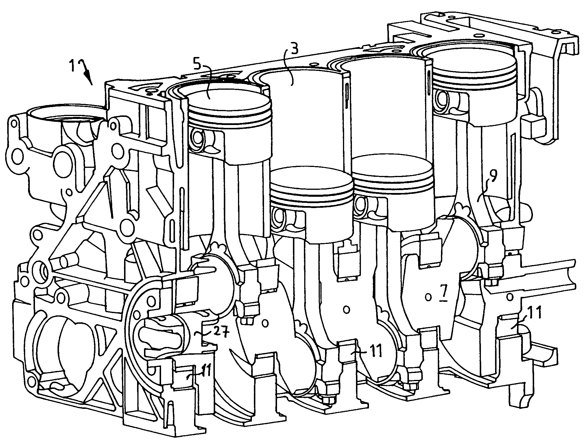
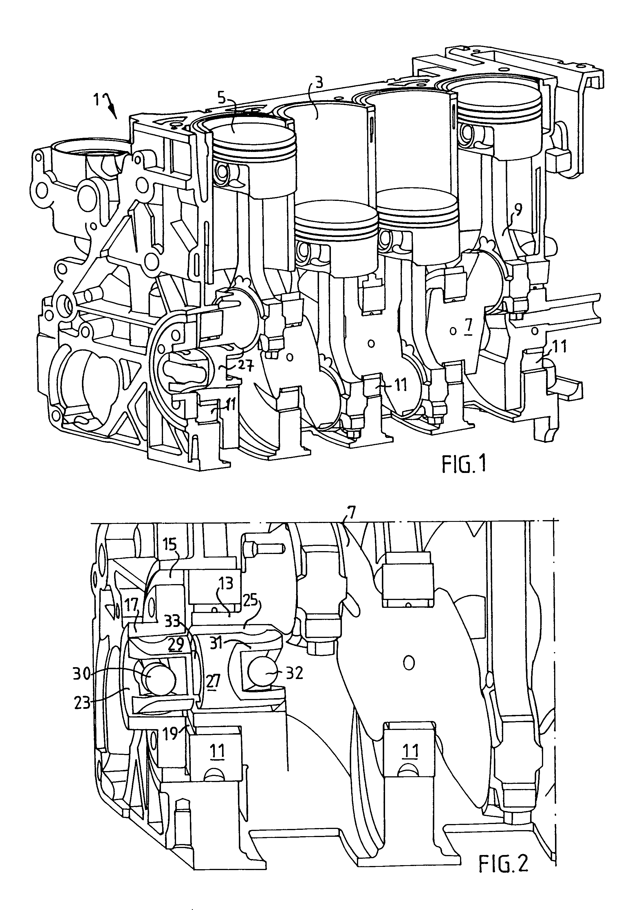
[0021]FIG. 1 shows in cross-section a combustion engine 1 of reciprocating type intended for a motor vehicle. The combustion engine has four cylinders 3 with associated pistons 5. These are in a conventional manner interconnected via a common crank shaft 7 by means of connecting rods 9. The crank shaft 7 is supported by a plurality of eccentric crankshaft bearings 11 arranged in the cylinder block of the combustion engine, which allow for rotation of the crank shaft 7 in the cylinder block. The force that is generated in the cylinders 3 is transmitted, via the connecting rods 9, to the crank shaft 7, and is forwarded to a not shown coupling / transmission for the operation of the wheels of the motor vehicle, but possibly also to a cam shaft for opening / closing of the valves of the reciprocating engine, or other devices that may take advantage of the energy produced by the reciprocating engine.

[0022]With eccentric crank shaft bearings 11 is meant eccentric supporting of the crank shaft...


PUM


Abstract

The invention relates to a reciprocating engine in a motor vehicle, comprising a coupling arrangement for transmission of a torque, from a crank shaft end, to a crank shaft flange supported in a cylinder block, the crank shaft end being movable in the radial direction with respect to the crank shaft flange, characterised in that the crank shaft end and the crank shaft flange together form an axially extended cavity adapted to contain the coupling arrangement.

Description

TECHNICAL FIELD[0001]The present invention relates to a reciprocating engine in accordance with the preamble of claim 1.BACKGROUND[0002]Conventional reciprocating engines usually operate at a constant compression ratio, i.e. the ratio between the maximum and the minimum volume above the piston. The higher compression ratio, the better efficiency and thereby a lower fuel consumption. However, a too high compression ratio can result in that the engine is subjected to “knocking”. The risk of “knocking” is greater at high engine power, for example high engine load, speed, and acceleration. Consequently, the compression ratio is set as high as possible, but yet as low as to avoid “knocking”.[0003]This implies, that when the engine power is low, i.e. during more normal conditions of operation, the compression ratio could in reality be higher without any risk of “knocking”. Thus, a reciprocating engine having a constant compression ratio does not work at an optimum during all conditions of...

Claims


Application Information

Patent Timeline
Patent Type & Authority Patents(United States)
IPC IPC(8): F02B75/22F02B75/04
CPCF02B75/047
Inventor GORANSSON, HANSDRANGEL, HANS
Owner SAAB AUTOMOBILE AB
Why Eureka
Try Eureka