System and method for maintaining heated intake air

a technology of intake air and system, applied in the direction of combustion air/fuel air treatment, machines/engines, mechanical equipment, etc., can solve the problems of reducing the efficiency of combustion engines, so as to reduce the nox production and fuel efficiency. the effect of greater fuel efficiency

Inactive Publication Date: 2007-05-08
FORD GLOBAL TECH LLC
View PDF20 Cites 20 Cited by
  • Summary
  • Abstract
  • Description
  • Claims
  • Application Information

AI Technical Summary

Benefits of technology

[0002]An internal combustion engine may utilize various types of combustion. For example, spark ignition (SI) of a homogenous mixture during the expansion stroke is one example. This method relies on a timed spark from a sparking plug in order to achieve ignition of an air / fuel mixture within the combustion chamber. Another type of combustion is homogeneous charge compression ignition (HCCI), which occurs when the temperature of the air / fuel mixture within combustion chamber attains the autoignition temperature of the specific fuel. HCCI can be used to provide greater fuel efficiency and reduced NOx production under some conditions.
[0006]In this way, it is possible to maintain a ready reserve of heated air in the hot-air passage thus providing the energy necessary for attaining autoignition of the air / fuel mixture when performing a substantially rapid transition from SI mode to HCCI mode.

Problems solved by technology

In addition, unheated air may also be provided.
However, the inventors herein have recognized that the heated air in the hot-air passage may become stagnant and therefore gradually cool during such operation.
As a result, the stagnant air in the hot-air passage may be of insufficient temperature or contain insufficient energy to achieve autoignition of the air / fuel mixture when needed.
Alternatively, the HCCI mode may be delayed until such air may be purged, thus delaying the desired transition.

Method used


Image

  • System and method for maintaining heated intake air
  • System and method for maintaining heated intake air
  • System and method for maintaining heated intake air

Examples


Embodiment Construction

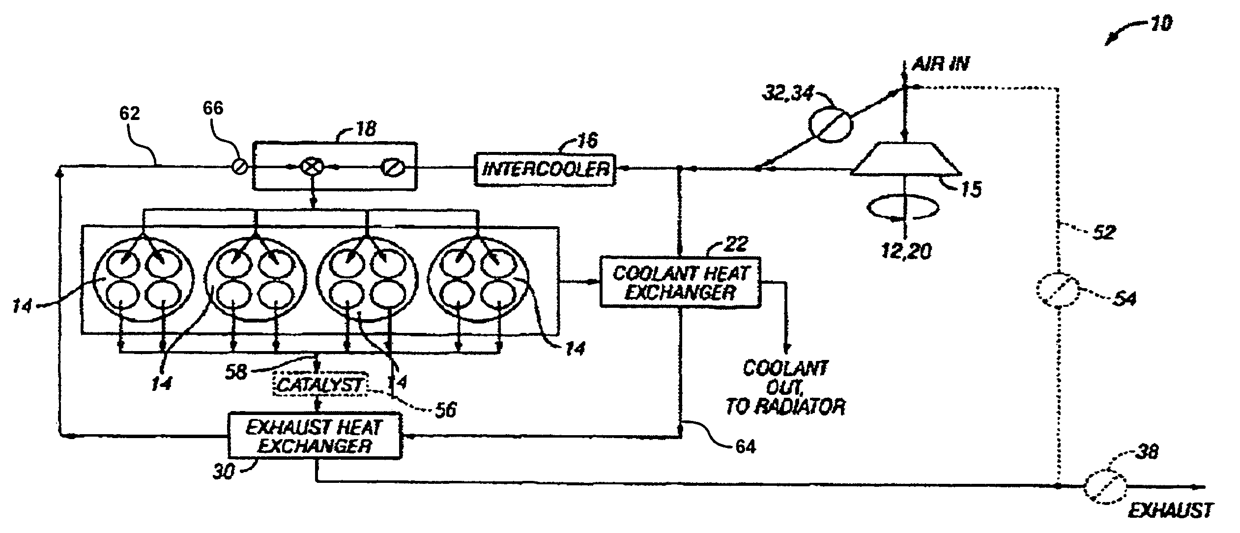
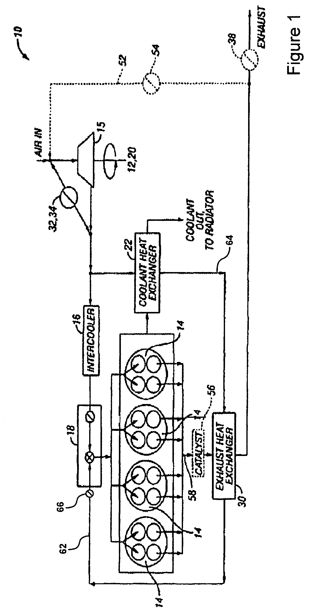
[0011]Referring to FIG. 1, a first embodiment of intake / exhaust system 10 with intake heating, inlet temperature and pressure controls, and intake air pressure boost using a supercharger 12 or an E-booster, are disclosed. For the embodiment of FIG. 1, the compressed intake air via air compressor 15 may include two flow paths (or routes) to engine cylinders 14. The first path may be through an intercooler 16, and then to control valves 18 and engine cylinders 14. Airflow through this path would be unheated air. The second path may be through coolant heat exchanger 22 and exhaust heat exchanger 30, and then to control valves 18 and engine cylinders 14. Various types of heat exchangers may be used, such as air to air or air to liquid. Airflow through this path would be heated air. In some examples, the arrangement of air through either intercooler 16 or through coolant heat exchanger 22 and exhaust heat exchanger 30 would allow low intake temperature operation in SI mode to reduce knoc...


PUM


Abstract

A system for an internal combustion engine, the engine having an intake and exhaust manifold, the system comprising a heat exchanger configured to extract energy from at least a heat source that heats a first portion of intake air, a spark plug coupled to the engine, an intake passage configured to deliver said first portion of heated intake air to the engine and to deliver a second portion of intake air which bypasses said heat source, and a controller configured to direct said second portion of intake air to the engine at least when utilizing said spark plug to initiate combustion and flame propagation of an air-fuel mixture, and to at least temporarily cause said first portion of intake air to flow during said spark ignition combustion so that a temperature of said first portion of intake air is maintained above a selected value.

Description

FIELD[0001]The present application relates to controlling engine operation during transitions between combustion modes.BACKGROUND AND SUMMARY[0002]An internal combustion engine may utilize various types of combustion. For example, spark ignition (SI) of a homogenous mixture during the expansion stroke is one example. This method relies on a timed spark from a sparking plug in order to achieve ignition of an air / fuel mixture within the combustion chamber. Another type of combustion is homogeneous charge compression ignition (HCCI), which occurs when the temperature of the air / fuel mixture within combustion chamber attains the autoignition temperature of the specific fuel. HCCI can be used to provide greater fuel efficiency and reduced NOx production under some conditions.[0003]In one example approach utilizing HCCI combustion, heat exchangers may be used to extract energy from the exhaust or engine coolant to heat a portion of the intake air and thereby provide heated air for attaini...

Claims


Application Information

Patent Timeline
Patent Type & Authority Patents(United States)
IPC IPC(8): F02G5/00F02M7/00
CPCF02M31/08Y02T10/126Y02T10/12
Inventor YANG, JIALIN
Owner FORD GLOBAL TECH LLC
Why Eureka
Try Eureka