
Light emitting diodes for high AC voltage operation and general lighting

a light-emitting diode, high-ac voltage technology, applied in the direction of lighting and heating apparatus, discharge tube luminescnet screens, lighting support devices, etc., can solve the problems of low efficiency, use of power converters, added volume, etc., and achieve the effect of enhancing heat transfer

Inactive Publication Date: 2007-05-08
SEOUL SEMICONDUCTOR
View PDF40 Cites 175 Cited by
  • Summary
  • Abstract
  • Description
  • Claims
  • Application Information

AI Technical Summary

Benefits of technology

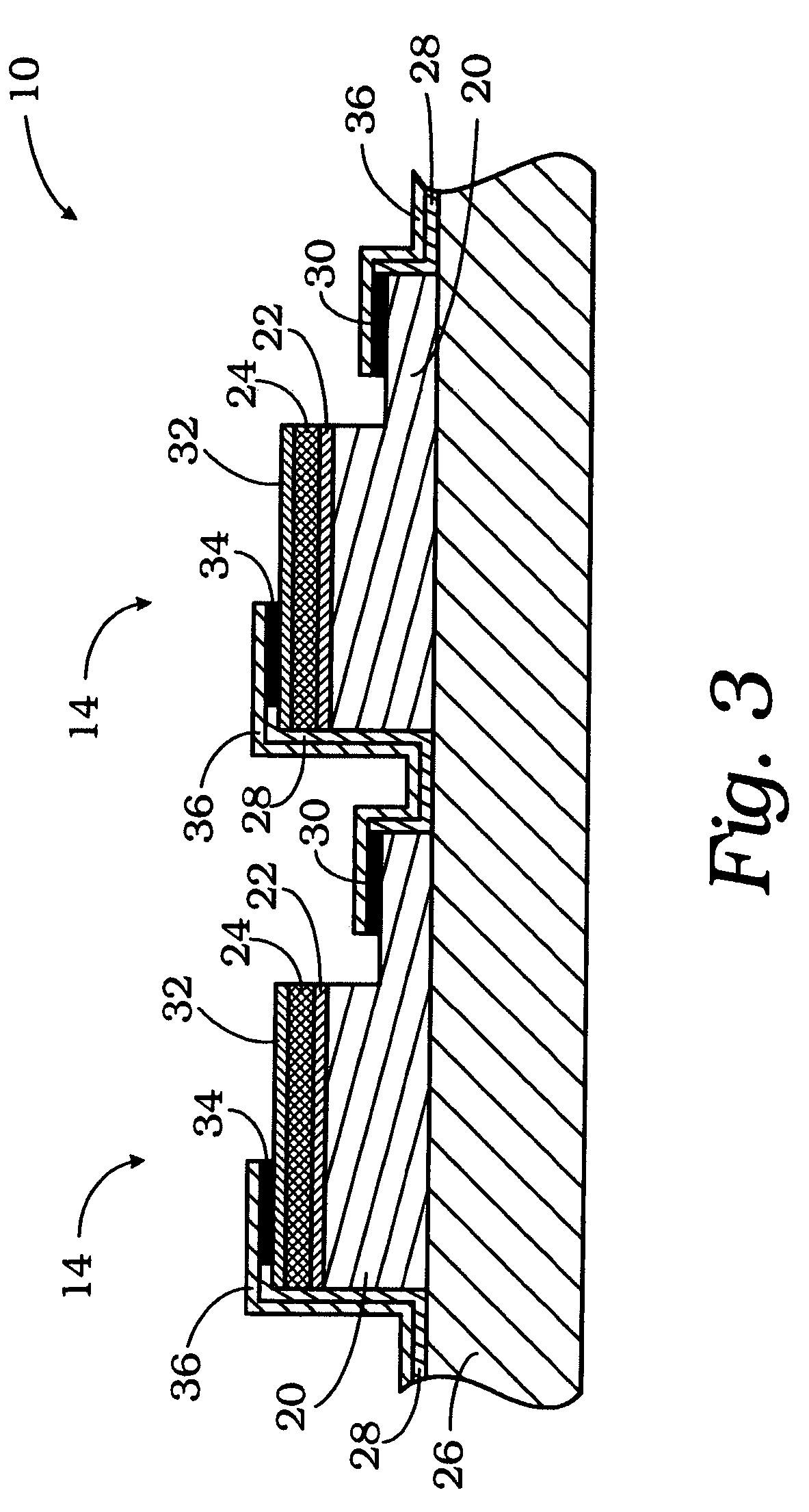
[0010]The single-chip AC LED device is formed by depositing layers of n-type semiconductor material, optically active layers and p-type semiconductor material in succession on an insulating transparent substrate. The chip is then flipped to be bonded to a submount and light is extracted from the top transparent substrate side. By flip-chip bonding, the AC LED device has more light extraction from the transparent substrate side without any light blocking by the contacts and interconnection metals. Flip-chip bonding the AC-LED on a highly thermal-conductive submount will also enhance the heat transferred away from the LED active region to the submount and then dissipated in the environment.

Problems solved by technology

Use of power converters have disadvantages such as added volume, added costs, and low efficiency, for example.
However, there are no new technologies involved in this type of “AC-LEDs” by ganging together a strand of LEDs and they are not suitable for lighting applications.
Hence it would not be viable economically or physically to replace an incandescent lamp by a strand of discrete of LEDs.

Method used


Image

  • Light emitting diodes for high AC voltage operation and general lighting
  • Light emitting diodes for high AC voltage operation and general lighting
  • Light emitting diodes for high AC voltage operation and general lighting

Examples


Embodiment Construction

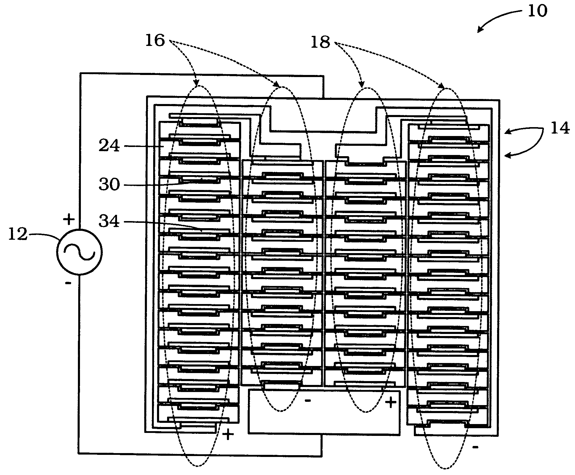
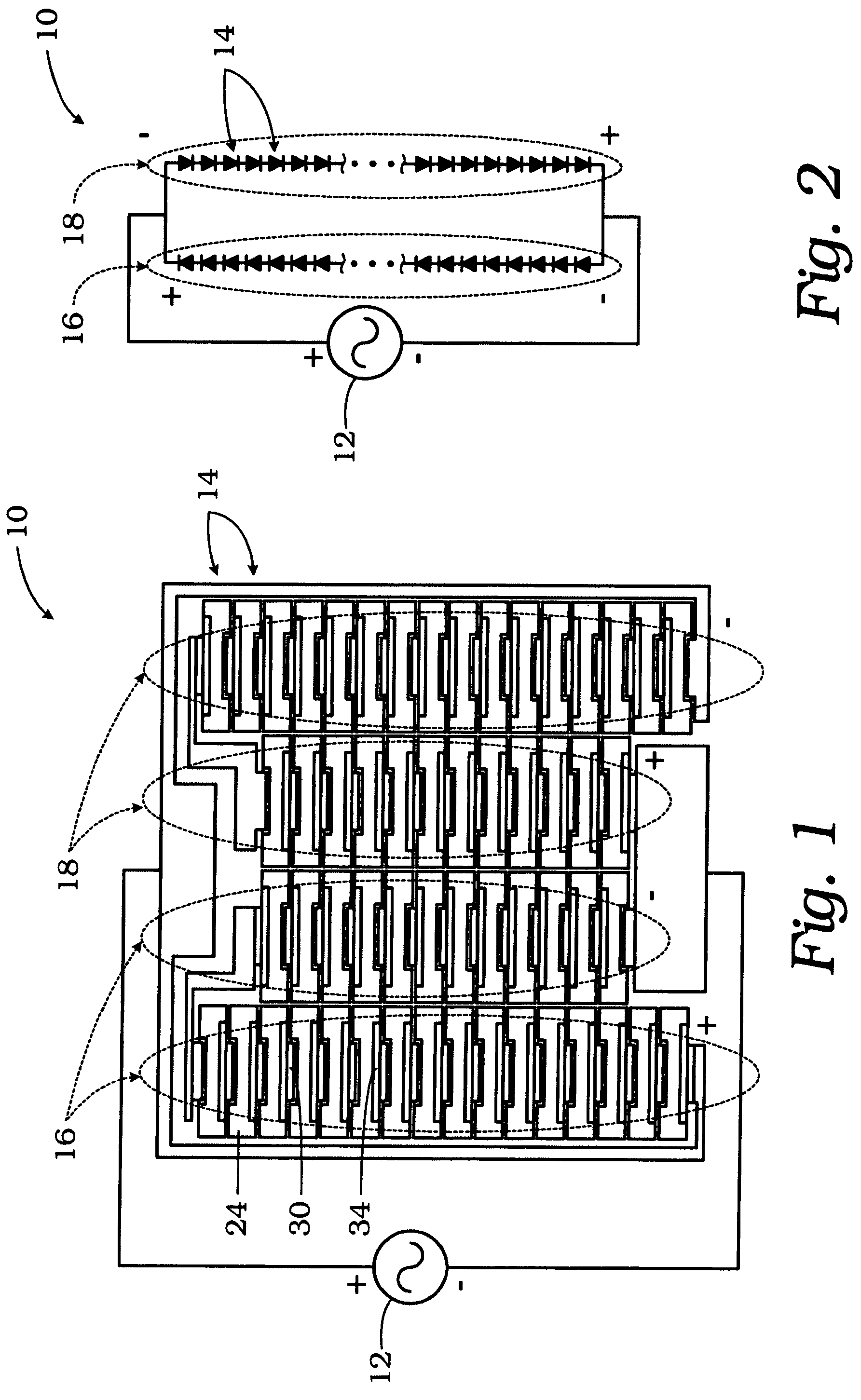
[0016]Referring to FIG. 1, a single-chip high voltage AC LED device 10 is illustrated connected to a high voltage AC power supply 12. As shown, the single-chip high voltage AC LED device 10 effectively consists of two arrays of series-connected individual smaller LEDs 14. The two arrays of series-connected individual LEDs are then connected to the opposite polarities of the high voltage AC power source 12. Each LED array could be made into one or many columns to fit the desired geometrical shape of the single-chip high voltage LED. In FIG. 1, each array consists of two columns for illustration.

[0017]Referring to FIGS. 1 and 2, the first array 16 of the single-chip AC LED device 10 provides a number of series-connected smaller LEDs 14. The cathode of one LED 14 is connected to the anode of the next LED to form the array 16. The array 16 of LEDs 14 presents a positive terminal corresponding to the cathode of the last LED (shown at the bottom of the first column of array 16 in FIG. 1 a...


PUM


Abstract

A single-chip integrated LED particularly adapted for direct use with a high voltage AC power comprises a plurality of series-connected LEDs arranged in two arrays and flip chip bonded to a transparent substrate. The opposite polarities of the arrays are connected together and then connected to the AC power source. During the positive half of the AC cycle, one array of LEDs is forward biased and energized, while the other array is reverse biased. During the negative half of the AC cycle, the other array of LEDs is forward biased and thus energized, while the first array is reverse biased and thus not energized. The arrays are alternately energized and de-energized at the frequency of the AC power source, and thus the single-chip integrated LED always appears to be energized.

Description

CROSS-REFERENCE TO RELATED APPLICATIONS[0001]The present application is a continuation-in-part application of Ser. No. 10 / 279,296, filed Oct. 24, 2002 now U.S. Pat. No. 6,957,899, which is hereby incorporated into the present application by reference.BACKGROUND OF THE INVENTION[0002]The present invention relates to single-chip light emitting diodes (LED), and more particularly to single-chip LEDs which can operate under standard alternating-current (AC) high voltage (110 V, 220 V, etc.) conditions for various applications, including general lighting.[0003]LEDs are used in displays, as indicator lights, for traffic lights, for communications, and for optical interconnects. With the realization of high brightness blue / green and violet LEDs made from the III-nitride semiconductor family InN, GaN, AlN and their alloys recently it is now possible that LEDs may be used for general lighting applications in residential houses and commercial buildings. LEDs have already found niche applicati...

Claims


Application Information

Patent Timeline
Patent Type & Authority Patents(United States)
IPC IPC(8): F21S13/14H01L27/15H05B44/00
CPCH05B33/0809H05B33/0821H01L24/24H01L24/82H01L27/156H01L2924/14H01L2224/24051H01L2924/01015H01L2924/01029H01L2924/01049H01L2924/01077H01L2924/01079H01L2924/01023H01L2924/01033H01L2924/01047H01L2924/014H01L2924/12041Y10S362/80H05B47/00H05B45/42
Inventor JIANG, HONGXINGLIN, JINGYU
Owner SEOUL SEMICONDUCTOR
Learn More