Blower fan

a blower fan and fan body technology, applied in the field of blower fans, can solve the problems of increased noise, non-guide area, and insufficient airflow of the air passing the blower fan, and achieve the effects of reducing power consumption rate, reducing noise, and reducing eddy curren

Active Publication Date: 2007-05-08
LG ELECTRONICS INC
View PDF10 Cites 9 Cited by
  • Summary
  • Abstract
  • Description
  • Claims
  • Application Information

AI Technical Summary

Benefits of technology

[0009]An object of the present invention is to provide a blower fan that can reduce the turbulence and the noise, which may be created at an air discharge side, by optimizing the designs of blades and a hub.
[0013]In another aspect of the present invention, there is provided a blower fan including: a shroud formed on an air intake side; a hub formed on an air discharge side to guide airflow being discharged; and a plurality of blades disposed between the shroud and the hub, wherein an outer end of each of the blades is inclined as it goes from a shroud side to a hub side, for reducing airflow noise.
[0015]According to the present invention, by the optimized design of the blades, eddy current that may be caused by the flow interference between the hub and the ends of the blades can be suppressed, while the airflow noise and the power consumption rate can be reduced.

Problems solved by technology

When the hub is designed having the outer diameter less than that of the blade, airflow of the air passing the blower fan cannot be sufficiently guided.
That is, although the air current is forcedly formed by the blades, there may be a non-guide area where the airflow cannot be guided by the hub.
This causes the noise to be increased.
Furthermore, since the air guided and discharged by the hub conflicts with the air guided and discharged by the blades, intensive turbulence is created to further increase the noise.
In addition, the eddy current deteriorates the operating efficiency of the fan, thereby increasing the power consumption.
The eddy current also causes the airflow loss.
This causes the increase of the power consumption.

Method used


Image

  • Blower fan
  • Blower fan
  • Blower fan

Examples


Embodiment Construction

[0023]Reference will now be made in detail to the preferred embodiments of the present invention, examples of which are illustrated in the accompanying drawings. Wherever possible, the same reference numbers will be used throughout the drawings to refer to the same or like parts.

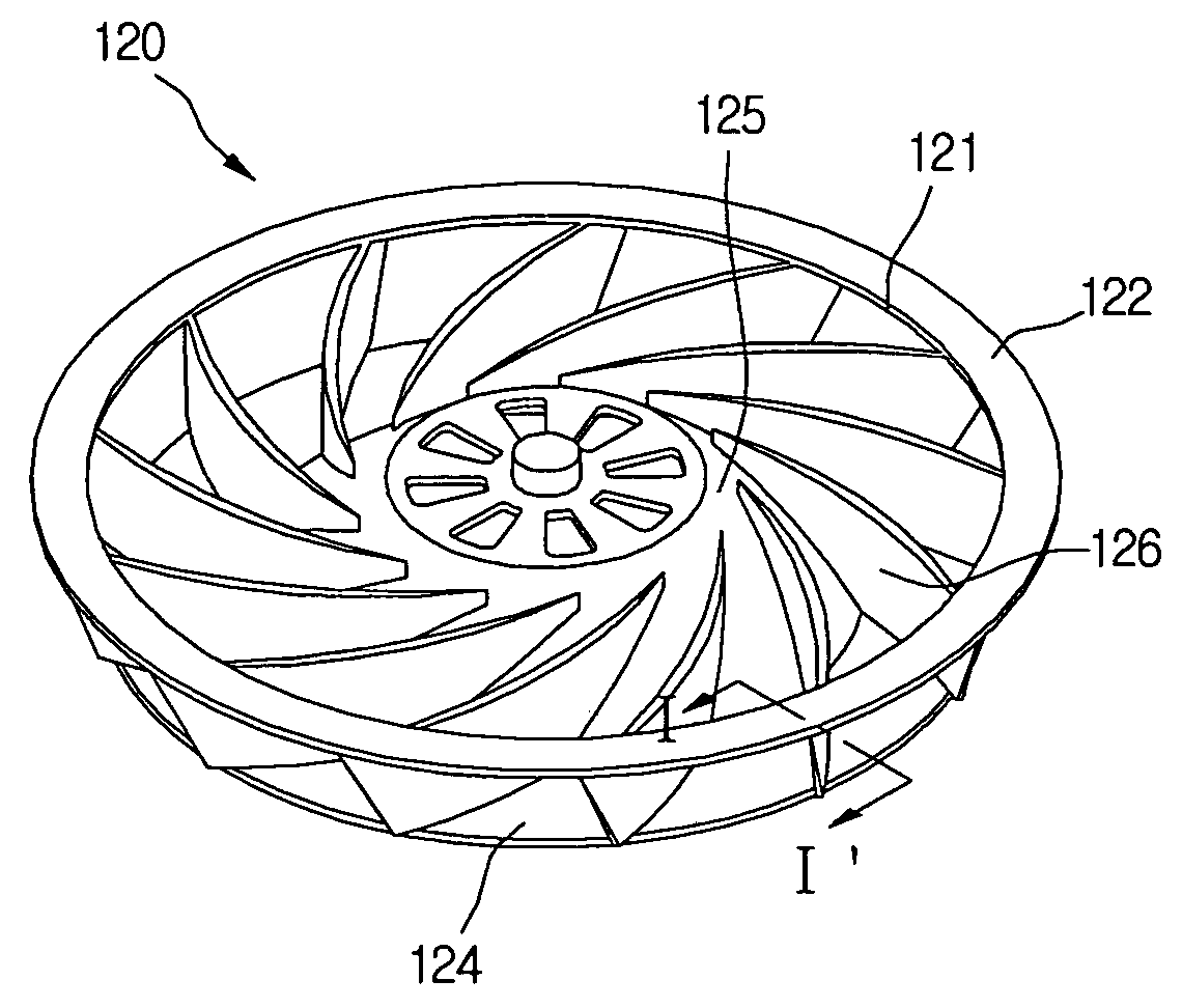
[0024]FIG. 1 shows a blower fan according to an embodiment of the present invention.

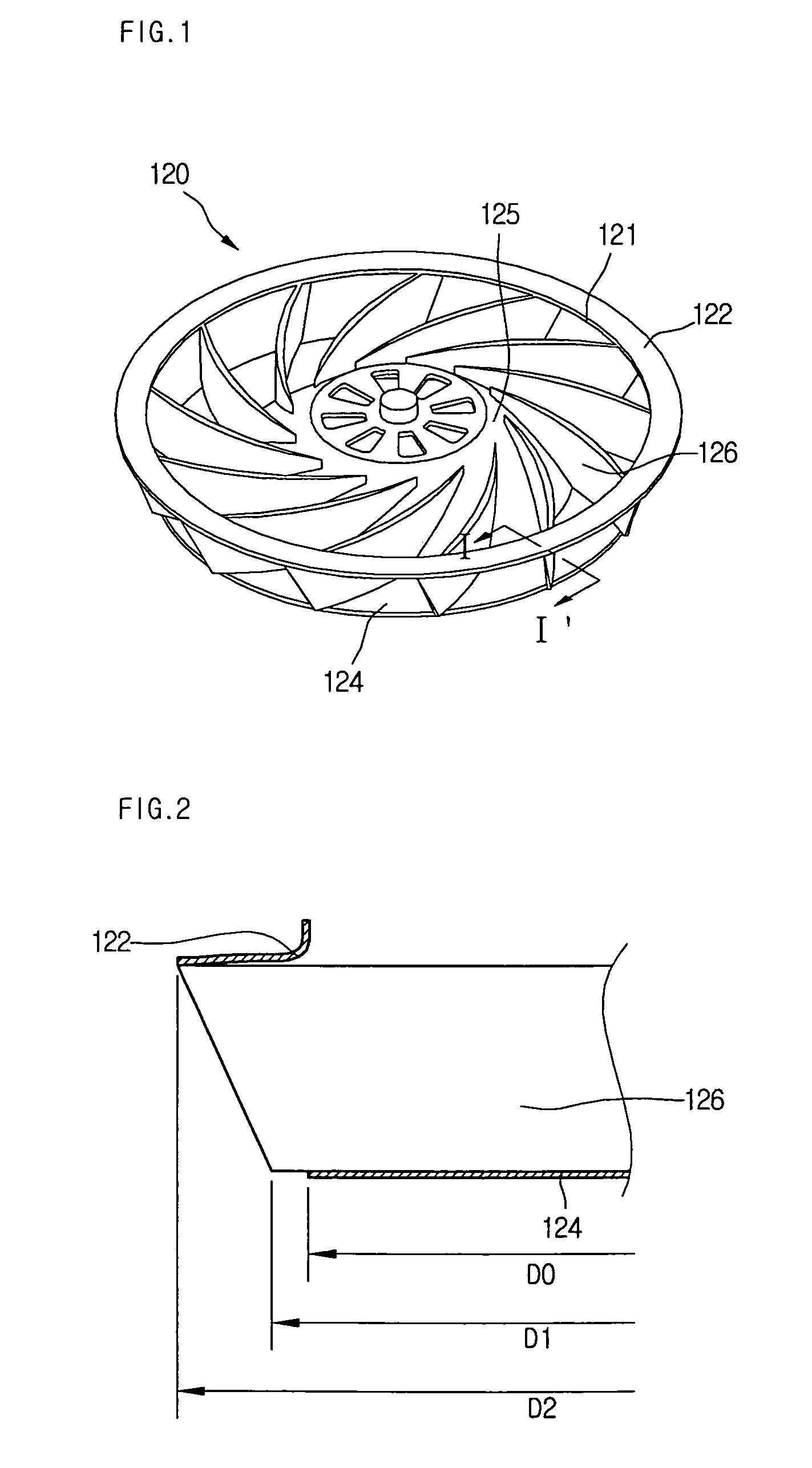
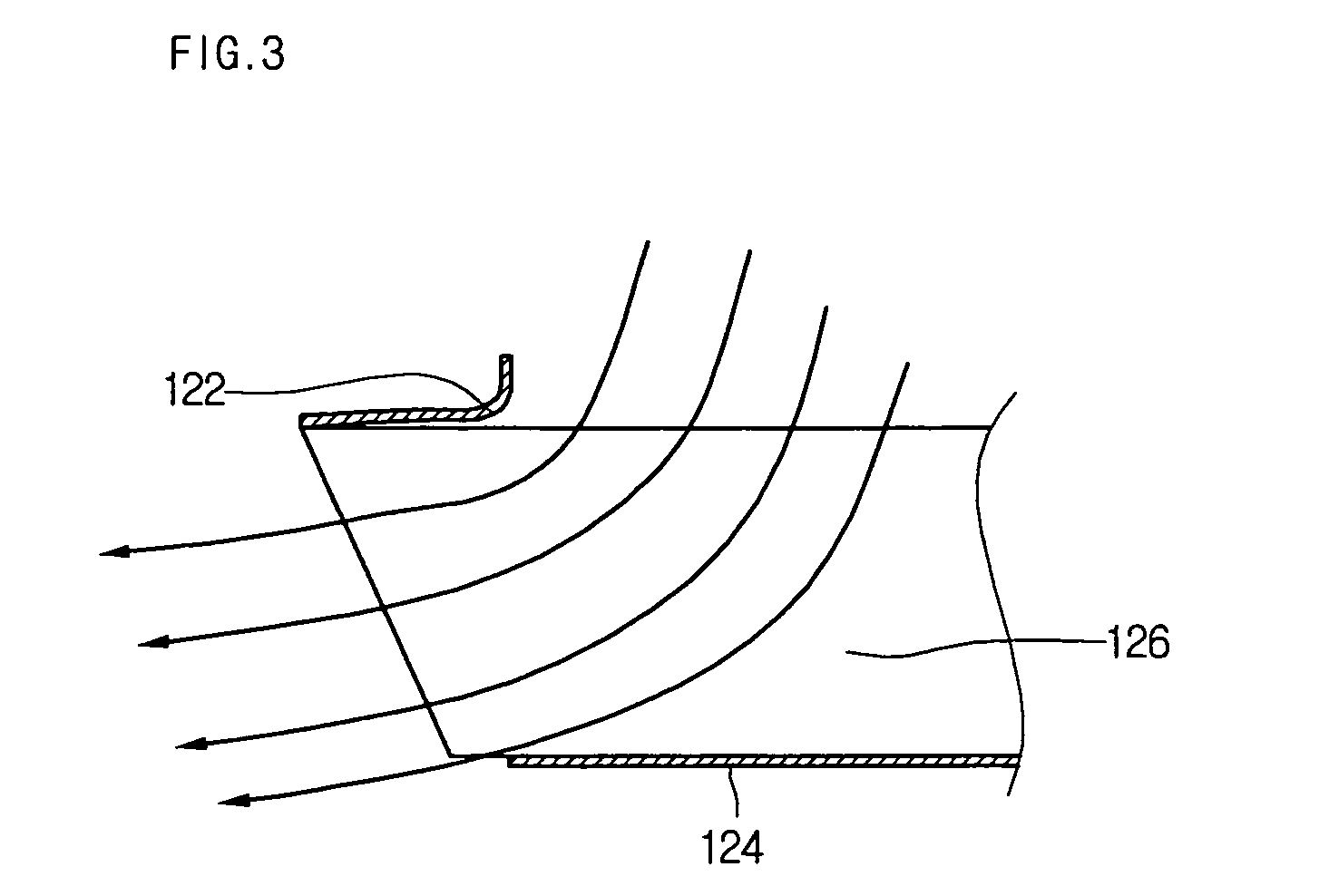
[0025]The inventive blower fan includes a shroud 122 formed on an air intake side, a hub 124 formed on an air discharge side, and a plurality of blades 126 formed between the shroud 122 and the hub 124.

[0026]Formed on a front surface of the shroud 122 is a bell mouth 130 (see FIG. 6) for effectively guiding the airflow of intake air.

[0027]In this embodiment, although a turbo fan is exampled as the inventive blower fan, the concepts of the present invention are not limited to the turbo fan. The concepts of the present invention can be applied to a variety of other types of blower fan.

[0028]As a feature of the present invention...


PUM


Abstract

A blower fan includes a shroud, a hub for guiding airflow being discharged, and a plurality of blades disposed between the shroud and the hub. A first outer diameter of a first portion, which is close to the hub, of the blade is different from a second outer diameter of a second portion, which is close to the shroud, of the blade.

Description

BACKGROUND OF THE INVENTION[0001]1. Field of the Invention[0002]The present invention relates to a blower fan, and more particularly, to a blower fan that is designed to improve the blowing efficiency by reducing airflow loss and reduce the noise generated when blades rotate.[0003]2. Description of the Related Art[0004]Generally, a blower fan is a device for forcedly producing air current. Particularly, a turbo fan that is one of the blower fans is designed to induce air in an axial direction, allow the induced air to make a turn by 90° and forcedly blow the same in a radial direction thereof.[0005]The blower fan includes a shroud formed on an air inducing side, a hub formed on an air discharge side, and a plurality of blades fixed between the shroud and the hub. To improve the productivity of the blower fan in a molding process and increase an airflow rate, the blower fan is designed having an inner diameter less than an outer diameter of the hub. In addition, the blade is designed...

Claims


Application Information

Patent Timeline
Patent Type & Authority Patents(United States)
IPC IPC(8): F04D29/30F24F13/24F04D29/28
CPCF04D29/281F04D29/30F24F13/24
Inventor LEE, JUNG WOOCHUNG, MOON KEECHIN, SIM WON
Owner LG ELECTRONICS INC
Why Eureka
Try Eureka