
Duplex electrical discharge machining

a technology of electrical discharge and machining, applied in the direction of electrical-based machining electrodes, electrical vibration holders, manufacturing tools, etc., can solve the problems of affecting accuracy and repeatability, reducing length and flexibility correspondingly, and not being flexibl

Active Publication Date: 2007-05-08
GENERAL ELECTRIC CO
View PDF18 Cites 41 Cited by
  • Summary
  • Abstract
  • Description
  • Claims
  • Application Information

AI Technical Summary

Benefits of technology

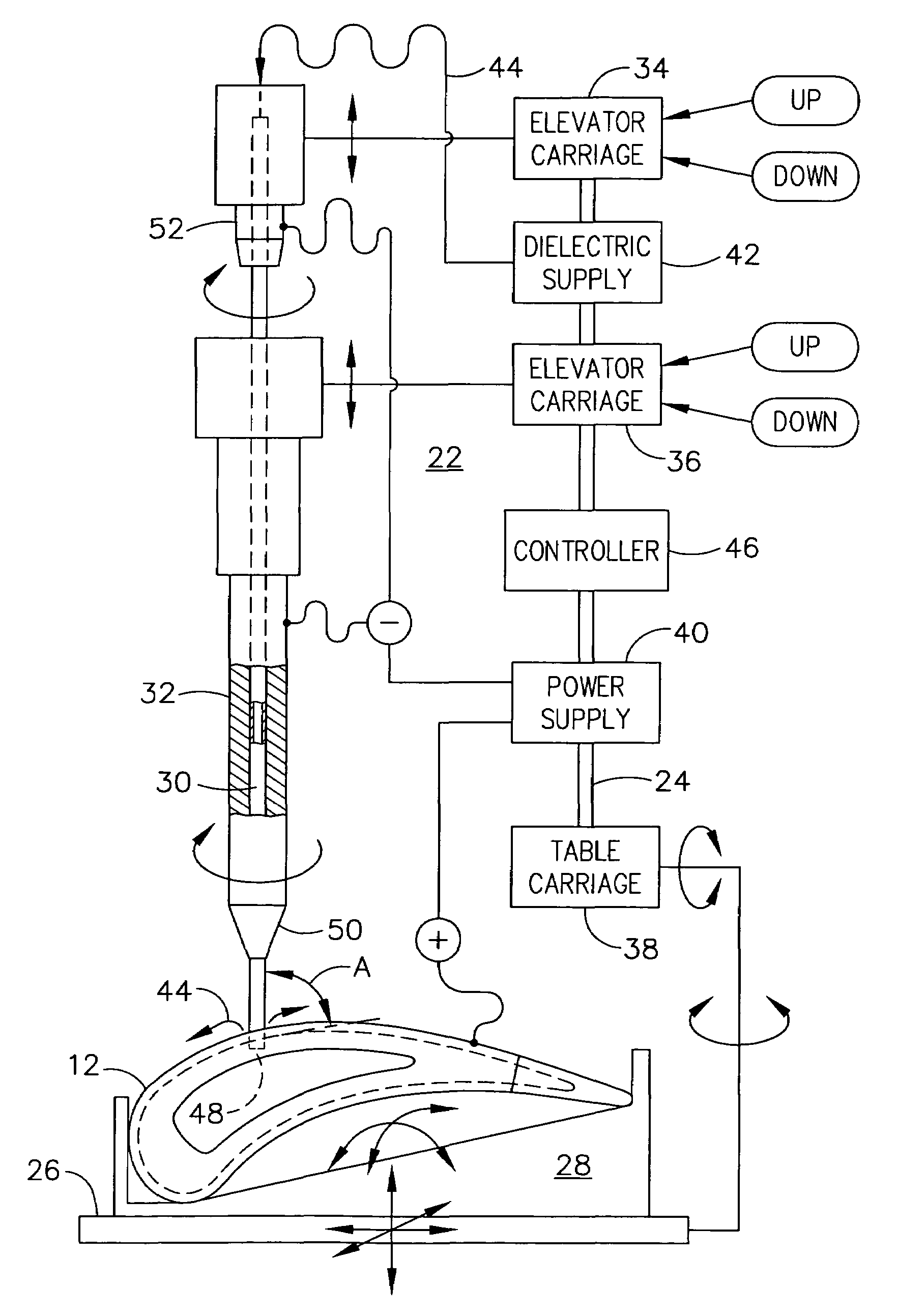
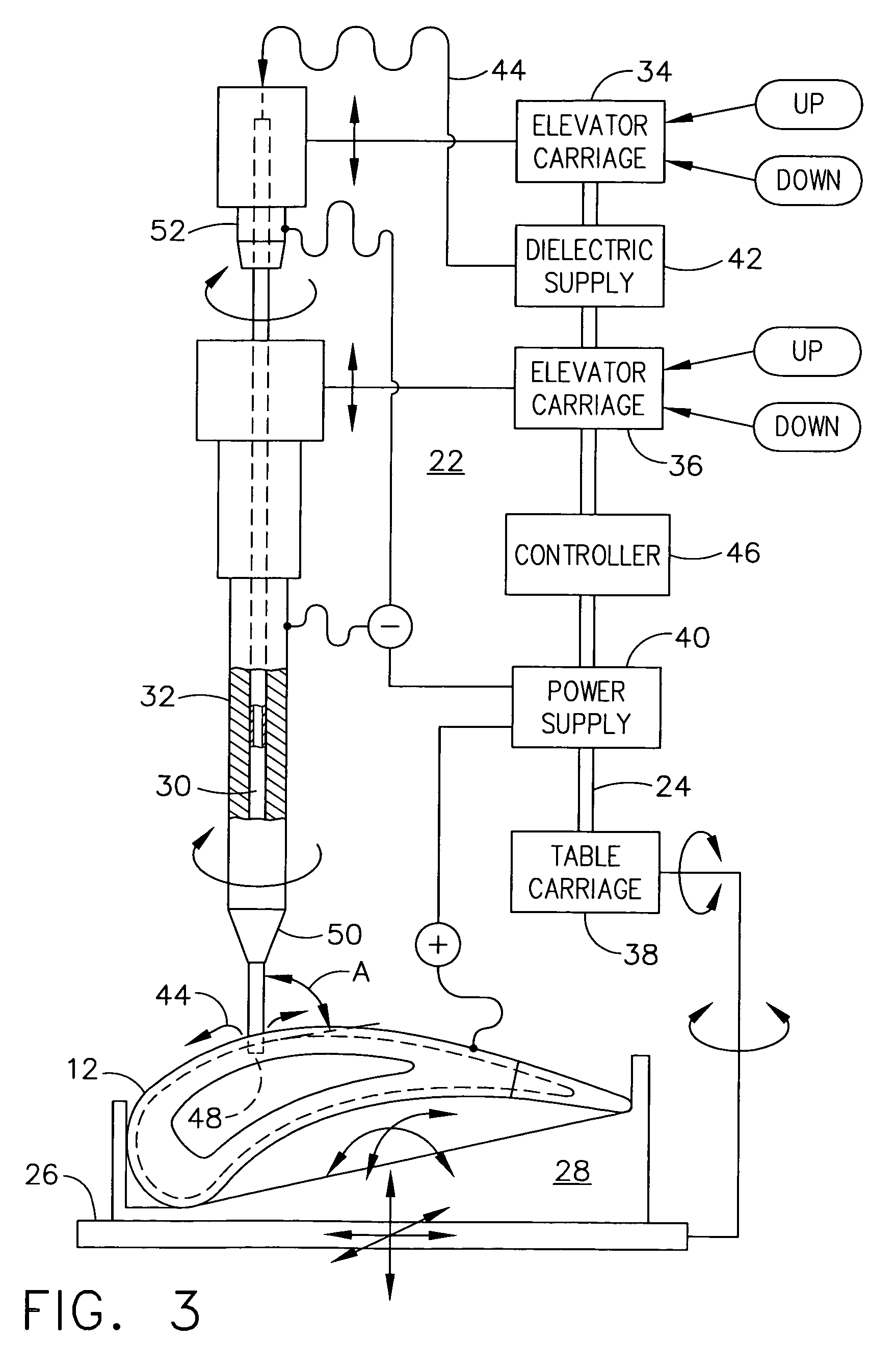
"The patent describes an electrical discharge machine that has two coaxial electrodes and carriages. The machine is designed to use a liquid dielectric and a workpiece that is electrically powered to create a duplex hole in the workpiece. The technical effect of this invention is to provide a more efficient and precise method for machining holes in workpieces."

Problems solved by technology

Such flexibility is typically not desirable since it adversely affects the accuracy and repeatability of EDM drilling.
However, the electrodes have a maximum length at the beginning of the drilling operation, with corresponding maximum flexibility, and are consumed during drilling which decreases their length and flexibility correspondingly.
Electrode flexibility becomes one problem due to the substantially high pressure of the dielectric channeled therethrough.
Since the electrode is a slender rod or column, it is subject to compressive buckling loads which can cause lateral deflection of the electrode that correspondingly shortens its effective length and withdraws the electrode tip slightly away from the workpiece, and affects EDM performance.
Since the film cooling air is discharged under pressure, small jets of air are developed and adversely affect the formation of a continuous external air film.
However, diffusion holes have complex configurations and cannot be formed by the simple tubular EDM electrode commonly used for cylindrical film cooling holes.
Instead, a specifically configured EDM electrode is required for machining the complex diffusion hole, but EDM wear of the electrode becomes more of a problem.
As the complex electrode wears it is not conveniently repairable, and must be replaced in whole.
The EDM comb electrodes may be economically manufactured in a stamping process, but nevertheless the combs wear during operation and must be replaced in whole.
Conventional EDM electrodes and apparatus therefor lack the versatility to economically drill or machine a multitude of film cooling holes having different orientations and different diffusion configurations.

Method used


Image

  • Duplex electrical discharge machining
  • Duplex electrical discharge machining
  • Duplex electrical discharge machining

Examples


Embodiment Construction

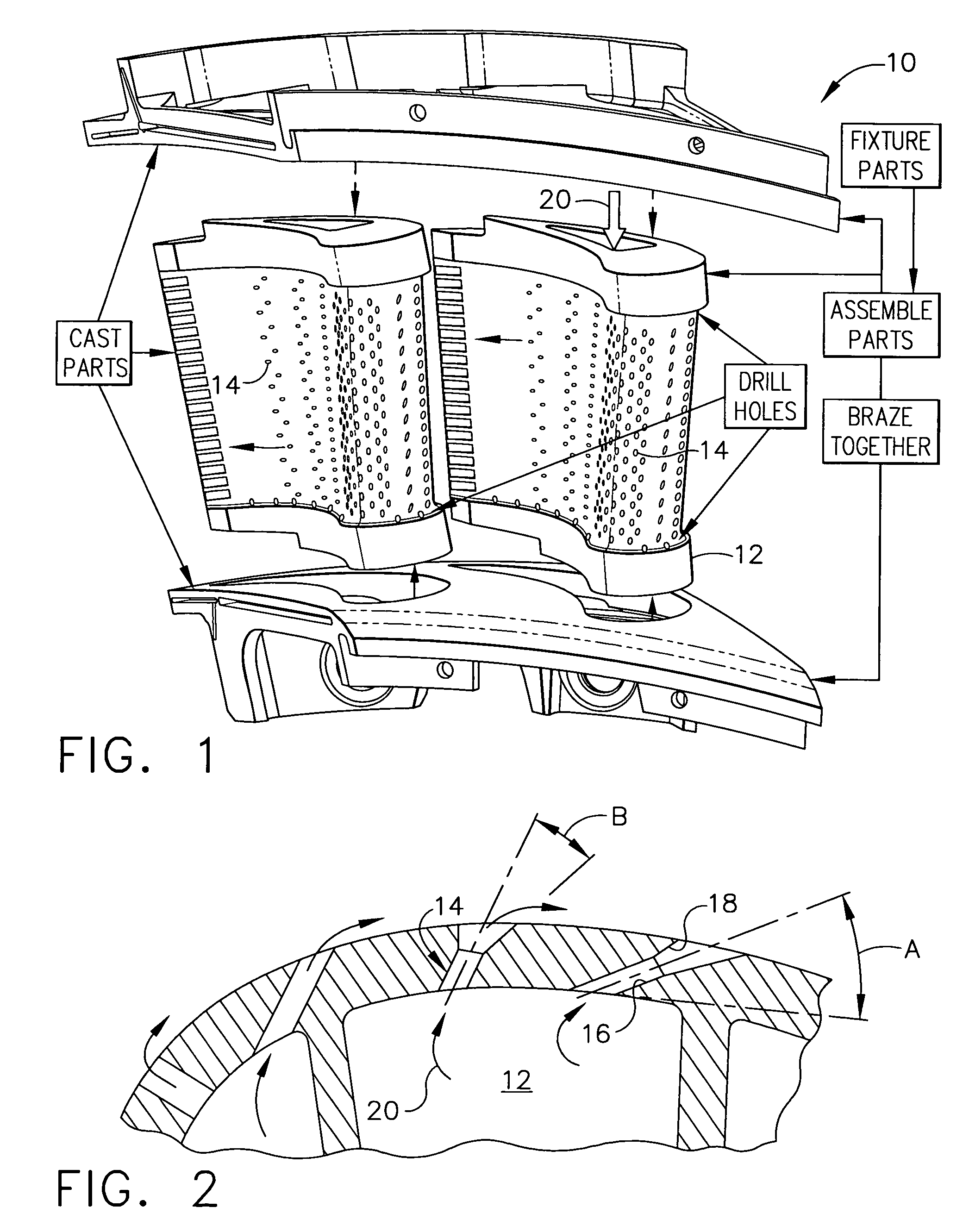
[0030]Illustrated schematically in FIG. 1 is an exemplary method of making a doublet segment of annular gas turbine engine high pressure turbine nozzle 10. The nozzle includes a pair of nozzle vanes 12 having typical airfoil configurations including a generally concave pressure side and an opposite, generally convex suction side extending axially in chord between opposite leading and trailing edges.

[0031]The vanes 12 extend in radial span between corresponding outer and inner band segments, which components are initially cast in a conventional manner and then assembled together and brazed to form a unitary assembly of the four parts.

[0032]Each vane 12 is initially cast hollow with a solid sidewall through which a multitude of film cooling holes 14 are typically drilled in corresponding rows along the longitudinal or radial span of each airfoil, and typically along both the pressure and suction sides thereof.

[0033]FIG. 2 illustrates exemplary configurations of some of these film cool...


PUM

PropertyMeasurementUnit
diameteraaaaaaaaaa
lengthaaaaaaaaaa
lengthaaaaaaaaaa

Abstract

An electrical discharge machine includes first and second coaxial electrodes and corresponding carriages. A liquid dielectric is channeled between the electrodes and a workpiece which are suitably electrically powered for machining a duplex hole in the workpiece.

Description

BACKGROUND OF THE INVENTION[0001]The present invention relates generally to electrical discharge machining (EDM), and, more specifically, to EDM drilling.[0002]Electrical discharge machining is a process in which a cathodic electrode is positioned atop an electrically conducting workpiece, and a liquid dielectric is channeled therebetween. Electrical current passes between the electrode and workpiece and locally erodes the workpiece for machining thereof. In a typical application, the electrode may be used for drilling a hole of any desired shape in the workpiece.[0003]For example, many gas turbine engine components include small holes therein through which cooling air is channeled during operation. The holes are small in diameter and typically range from 10–80 mils (0.2–2.0 mm), and require a slightly smaller diameter EDM electrode.[0004]The narrow electrodes are consumed during machining, and are therefore initially relatively long in length which typically ranges from about 12–16...

Claims


Application Information

Patent Timeline
Patent Type & Authority Patents(United States)
IPC IPC(8): B23H9/10B23H1/04B23H7/26B23H9/14
CPCB23H1/00B23H1/04B23H7/265B23H9/10B23H9/14B23H2400/10
Inventor BALL, GLENN EDWARDGLEASON, MARK JOSEPHWEBB, BARRY JOE
Owner GENERAL ELECTRIC CO
Learn More