Optical reproducing apparatus

a technology of optical disk and reproducing apparatus, which is applied in the direction of digital signal error detection/correction, instruments, recording signal processing, etc., can solve the problems of false tracking error signal, imbalance of reflected light intensity distribution, and confusion among common users

Inactive Publication Date: 2007-05-08
HITACHI CONSUMER ELECTRONICS CORP
View PDF15 Cites 22 Cited by
  • Summary
  • Abstract
  • Description
  • Claims
  • Application Information

AI Technical Summary

Benefits of technology

[0022]In view of the above-mentioned problems, the object of the present invention is to provide a small-size, high-performance optical reproducing apparatus that uses a hologram laser module and can be applied to the DVD Multi drive.

Problems solved by technology

A problem has been pointed out that these existing plural standards introduce confusions among common users, and recently optical disk apparatuses in conformity to a standard called “DVD Multi,” indicating capability of recording and reproducing all of these optical disks, have been released as commercial products.
The push-pull method is a method in which imbalance of a reflected light intensity distribution generated on a pupil plane of the objective lens resulting from diffraction of light by the guide groove and an interference effect between beams of the diffracted light.
With respect to the tracking error signal detection by the push-pull method, a problem has been pointed out for many years.
This is a problem that a false tracking error signal (hereinafter referred to as “offset”) is generated because, when the objective lens is moved in connection with the tracking operation (hereinafter referred to as “lens shift”), the optical spot on the photodetector also moves in accordance with the movement.
However, this method is incomplete in suppressing the offset as compared with the differential push-pull method.
Therefore, this method may turn to be insufficient in cases where the push-pull signal amplitude is small, to be more precise, a case where the guide groove-pitch is narrow as compared with the focused spot, a case where the guide groove is shallow, a case where the guide groove width is narrow as compared with the guide groove pitch, etc., that is, cases where the remaining offset becomes notably large.
Further, since the signal is obtained not from the distribution but from the total light quantity, there does not occur offset that is caused by the lens shift and may become a problem in the push-pull method.
Further, since this method requires that the reflected light quantity when the spot is on the guide groove differ from the reflected light quantity when the spot is between the guide grooves, if the guide groove width and a spacing between the guide grooves are the same in dimension, the signal cannot be detected theoretically.
For this reason, the method that uses the polarization-dependent diffraction grating reduces the effect of suppressing the offset.
Further, in DVD-R / RW etc. whose guide groove is shallow, the tracking error signal amplitude becomes extremely small.
For these reasons, this conventional example is not suitable for recording disks, and hence cannot be applied to the DVD Multi drive.
Further, since it is necessary to mount the polarization-dependent diffraction grating on the objective lens to be an integrated combination, its weight will be a problem in enhancing the speed in the future.
Moreover, since the polarization-dependent diffraction grating is independent from the module wherein the semiconductor laser and the photodetector were integrated, it is likely that displacement between the polarization-dependent diffraction grating and the module due to temperature variation and / or change over time will occur.
The occurrence of the displacement deteriorates accuracy of focus control of the focused spot and of the tracking control, causing degradation of the reproduced signal.
Therefore, positions of the sub spots that are necessary for the differential push-pull method are different for DVD-RAM and for DVD-RW etc., and hence the differential push-pull method cannot be compatible for the two kinds of systems.

Method used


Image

  • Optical reproducing apparatus
  • Optical reproducing apparatus
  • Optical reproducing apparatus

Examples


Embodiment Construction

[0070]Hereafter, embodiments according to the present invention will be described referring to the figures.

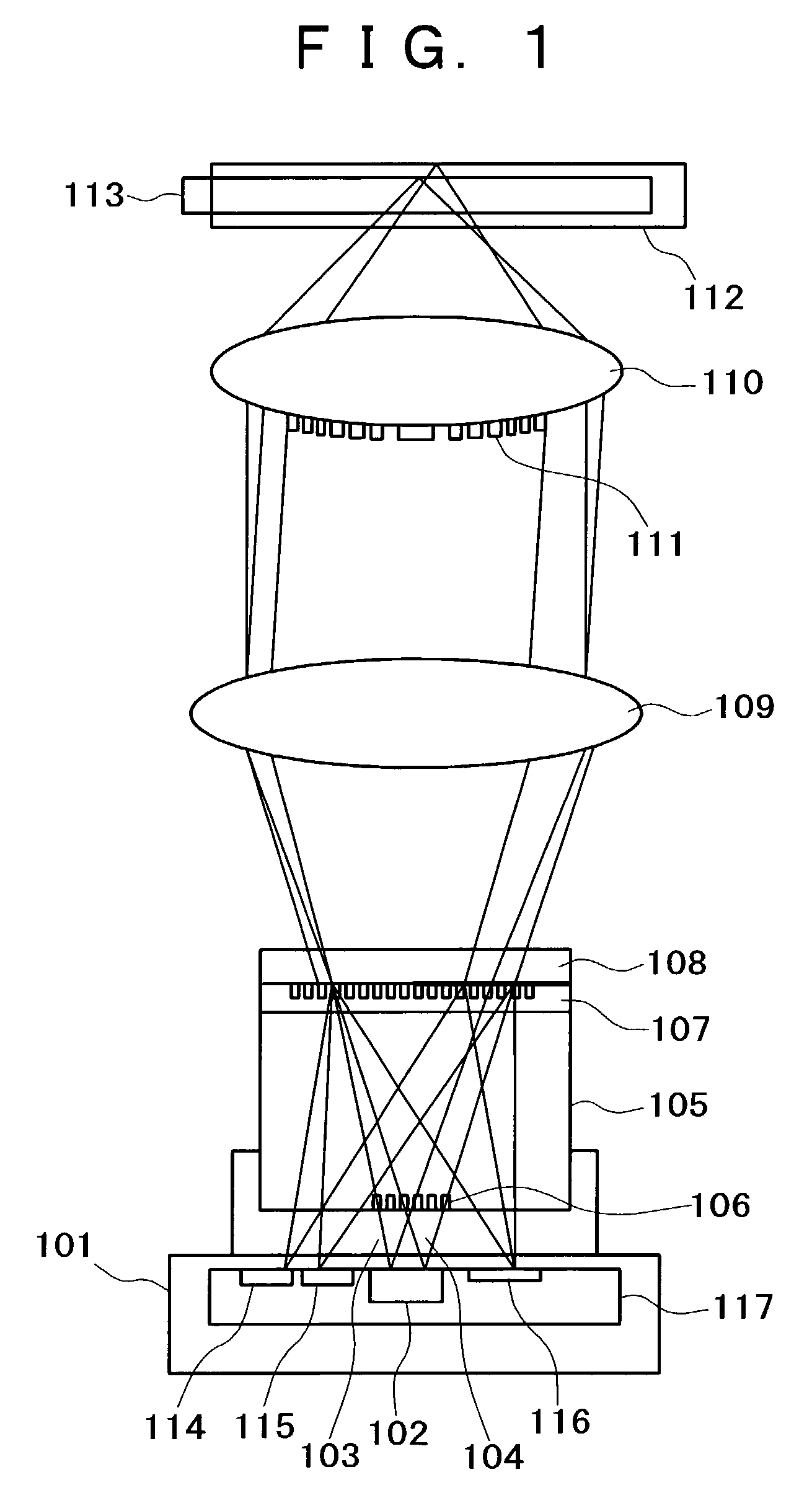
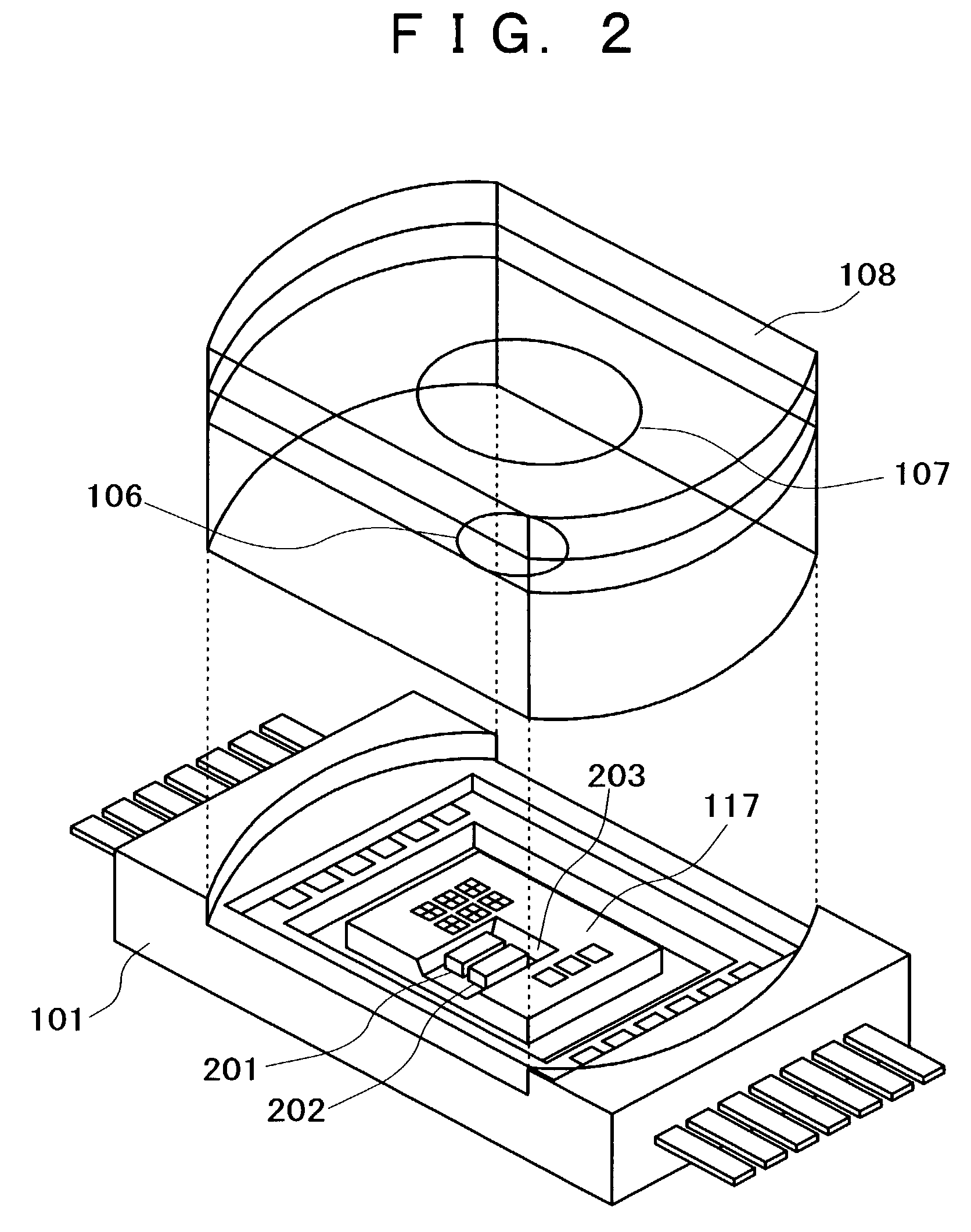
[0071]FIG. 1 shows a fundamental embodiment of the optical reproducing apparatus according to the present invention. In a two-wavelength hologram laser module 101, infrared-laser light 103 and red laser light 104 are emitted from a two-wavelength semiconductor laser 102. In practice, although it is not necessary to emit these beams of light simultaneously and only one of tem that is necessary needs to be emitted, here the both beams of light are shown for the convenience of illustration. Each light enters a complex diffraction grating 106 formed on the diffraction grating substrate 105 and is divided into five beams, not shown in the figure, at each wavelength. Next, these beams of emitted light pass through the polarization-dependent diffraction grating 107, and are emitted from the two-wavelength hologram laser module 101 via a quarter-wave plate 108. At this time, the polari...


PUM

PropertyMeasurementUnit
wavelengthsaaaaaaaaaa
current sizeaaaaaaaaaa
sizeaaaaaaaaaa

Abstract

An optical reproducing apparatus that uses a hologram laser module and is applicable to a DVD Multi drive, wherein five sub spots of light in total that are most suitable to perform the differential push-pull tracking both for DVD-RAM and for DVD-R / RW are irradiated on the disk, respectively, and influence of several sub spots that are unnecessary in recording and reproducing a disk is canceled out by calculation, to realize an optical head that is compatible with the DVD Multi drive using a hologram laser module, and thereby providing a small-size, high-performance optical reproducing apparatus.

Description

BACKGROUND OF THE INVENTION[0001]1. Field of the Invention[0002]This invention relates to an optical disk apparatus, and more particularly to an optical head technology whereby plural classifications of optical disks are reproduced.[0003]2. Description of Related Art[0004]As commercial optical disks of a current size of 120 mm, there stand abreast a variety of standards such as DVD-ROM, DVD-RAM, DVD-R, DVD-RW, CD-R, and CD-RW in addition to the conventional music CD and CD-ROM according to the difference in recording density, capability of recording, erase, and rewriting, reliability, and distinction of application. A problem has been pointed out that these existing plural standards introduce confusions among common users, and recently optical disk apparatuses in conformity to a standard called “DVD Multi,” indicating capability of recording and reproducing all of these optical disks, have been released as commercial products.[0005]As one of differences among the above-mentioned plu...

Claims


Application Information

Patent Timeline
Patent Type & Authority Patents(United States)
IPC IPC(8): G11B7/09G11B7/00G11B7/095G11B7/125G11B7/135
CPCG11B7/094G11B7/0943G11B7/1205G11B7/1263G11B7/1275G11B7/131G11B7/1353G11B7/1374G11B7/005G11B7/0903G11B7/0906G11B19/12G11B2007/0006G11B7/123
Inventor SHIMANO, TAKESHISUKEDA, HIROFUMI
Owner HITACHI CONSUMER ELECTRONICS CORP
Why Eureka
Try Eureka