
Image compression coding apparatus and control method therefor

a technology of image compression and coding apparatus, applied in the direction of electrical apparatus, instruments, computing, etc., can solve the problems of not easy to perform compression coding processing, feedback method takes more time overhead spent on trial compression coding processing, degree of freedom, etc., to achieve high real-time operability and performance, the effect of reducing the number of coding errors

Active Publication Date: 2007-05-08
CANON KK
View PDF15 Cites 28 Cited by
  • Summary
  • Abstract
  • Description
  • Claims
  • Application Information

AI Technical Summary

Benefits of technology

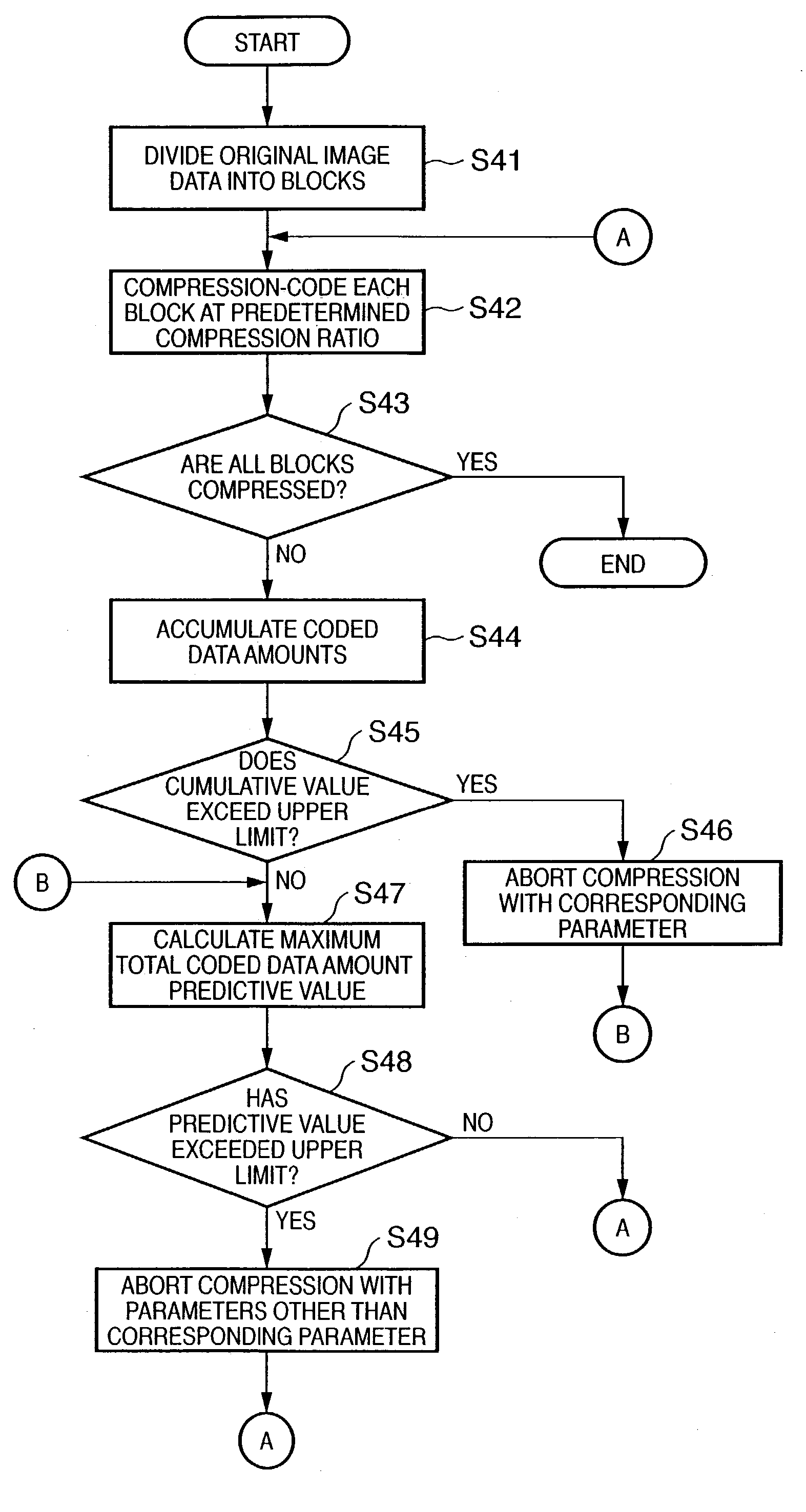
[0028]The present invention has been proposed to solve the conventional problems, and has as its object to provide an image compression coding apparatus and a control method for the apparatus. According to the image compression coding apparatus and the control method for the apparatus of the present invention, in a system like a digital imaging device which is required to have high real-time operability and performance, when compression coding processing is to be performed while information amount control using a feedback technique with high prediction precision is realized, a coded data with the minimum coding distortion within an allowable compression ratio range can be obtained while a deterioration in the performance of the system is minimized.
[0032]An image compression coding apparatus according to the present invention is comprising block formation means for dividing input image data into blocks each having a predetermined size, compression coding means for compression-coding the image data for each divided block on the basis of a plurality of compression coding parameters and outputting a plurality of coded data, re-compression coding means for re-compression-coding the coded data, coded data amount accumulation means for calculating a cumulative data amount of the coded data for a compression-coded block, upper limit setting means for setting a total coded data amount upper limit for input image data, threshold calculation means for sequentially calculating a threshold not more than the upper limit on the basis of the upper limit, a minimum coded data amount per a predetermined number of blocks, and the number of compression-coded blocks, and control means for, when the cumulative data amount exceeds the threshold, changing the compression coding parameter used by the compression coding means and causing the re-compression coding means to perform re-compression coding.

Problems solved by technology

Even if allowable compression ratio upper and lower limits are set in this manner, it is not easy to perform compression coding processing such that the compression ratios for all original image data supplied fall within that range.
Theoretically, however, this feedback method takes more time overhead spent for trial compression coding processing.
Provided that a still image compression coding scheme like the one described above with a limitation being imposed on the degree of freedom of coding parameters is used, the above algorithm for sequentially correcting a coding parameter cannot be used in any of the above conventional techniques.
As a consequence, local variations in compression coding distortion occur in a reconstructed image obtained by decompression / decoding processing, and hence it is not preferable to apply such compression coding processing to a digital imaging device.
However, as the number of parallel operations increases, the overhead in transferring and storing coded data in a memory through a transmission path increases, resulting in a deterioration in system performance.
However, the time spent for this redoing, i.e., re-coding processing, directly leads to a deterioration in system performance.

Method used


Image

  • Image compression coding apparatus and control method therefor
  • Image compression coding apparatus and control method therefor
  • Image compression coding apparatus and control method therefor

Examples


first embodiment

[0068]FIG. 16 is a block diagram showing the arrangement of an image compression coding apparatus according to the present invention. The image compression coding apparatus according to this embodiment is comprised of a block formation unit 211 (block formation means), upper limit setting unit 212 (upper limit setting means), block count setting unit 213 (block count setting means), compression coding unit 214 (compression coding means), data amount accumulation unit 215 (data amount accumulation means), minimum total coded data amount prediction unit 216 (minimum total coded data amount prediction means), and control unit 217 (control means).

[0069]The block formation unit 211 divides original image data 221 input to the image compression coding apparatus of this embodiment into blocks each having a predetermined size, and outputs them to the compression coding unit 214. The total coded data amount upper limit obtained when block-divided original image data completely coded is set i...

second embodiment

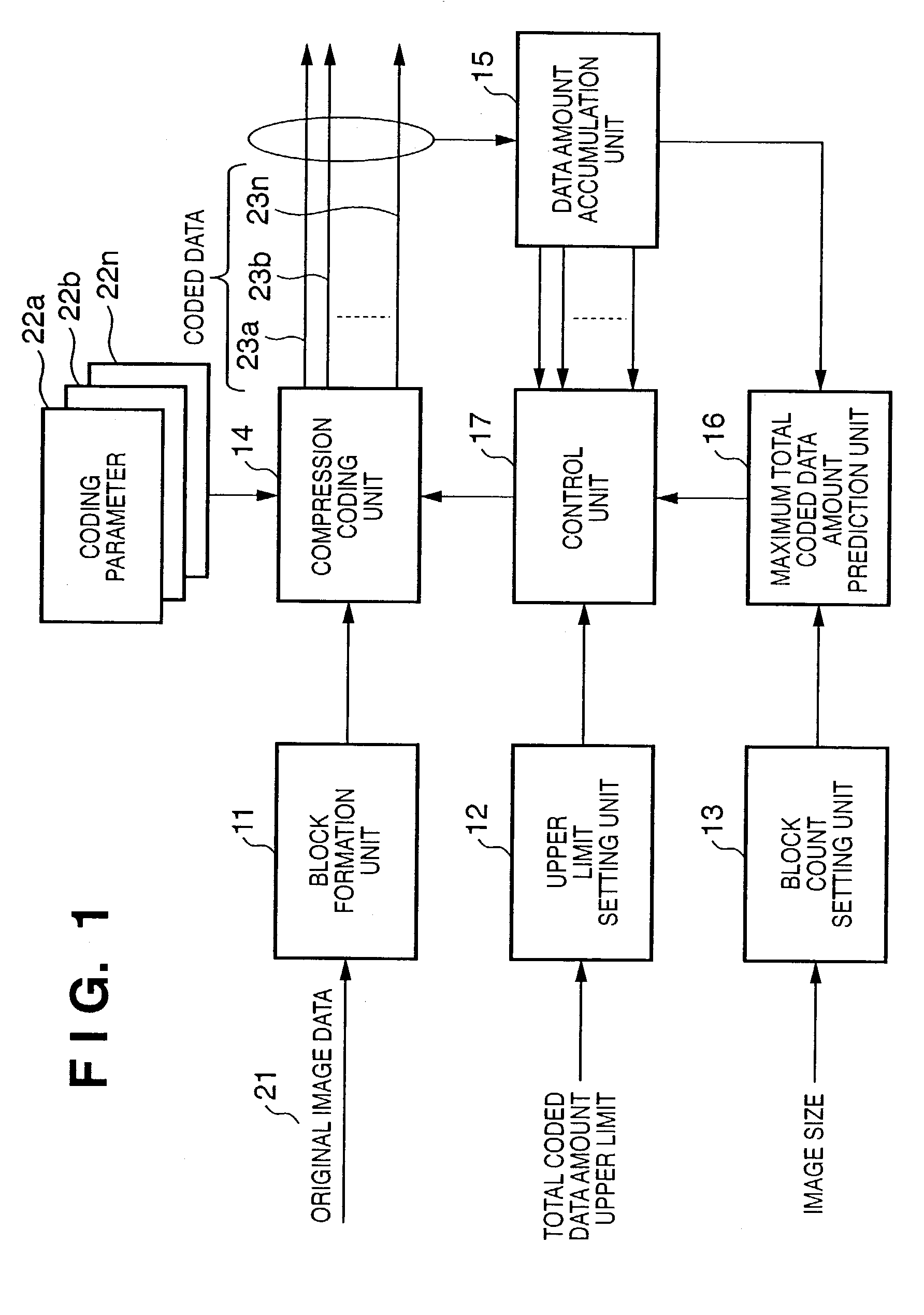
[0083]FIG. 1 is a block diagram showing the arrangement of an image compression coding apparatus according to the present invention. As shown in FIG. 1, the image compression coding apparatus according to this embodiment is comprised of a block formation unit 11 (block formation means), upper limit setting unit 12 (upper limit setting means), block count setting unit 13 (block count setting means), compression coding unit 14 (compression coding means), data amount accumulation unit 15 (coded data accumulation means), maximum coded data amount prediction unit 16 (maximum coded data amount prediction means), and control unit 17 (control means).

[0084]The block formation unit 11 divides original image data 21 input to the image compression coding apparatus according to this embodiment into blocks each having a predetermined size, and outputs them to the compression coding unit 14. The total coded data amount upper limit obtained when block-divided original image data completely coded is...

third embodiment

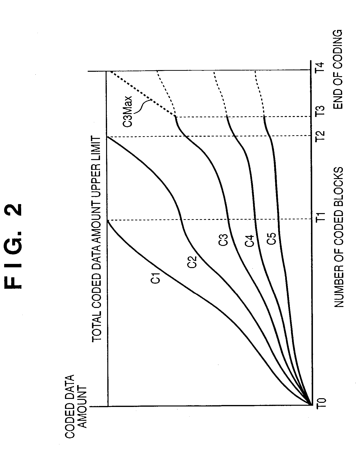
[0115]The time required for the image compression coding apparatus of this embodiment to perform compression coding processing for an original image will be described below. FIG. 7 is a graph for explaining the relationship between the cumulative coded data amount value (ordinate) of the coded data generated by the image compression coding apparatus and the time (abscissa) required for compression coding processing for an original image. FIG. 8 is a view showing relative positions T0, T1, T2, and T3 of blocks, on the original image, which have been compression-coded at times t0, t1, t2, and t3 on the graph in FIG. 7, and three divided areas A, B, and C on two-dimensionally expressed original image data.

[0116]A coded data C1 is output outside the image compression coding apparatus according to this embodiment until time t1 on the graph of FIG. 7. A coded data C2 is then temporarily stored in the memory 38 in FIG. 2. When compression coding processing is completed up to the block T1 ...


PUM


Abstract

An image compression coding apparatus which can obtain coded data with minimum coding distortion within an allowable compression ratio range while minimizing a deterioration in the performance of a system, and a control method for the apparatus.

Description

FIELD OF THE INVENTION[0001]The present invention relates to an image compression coding apparatus which compression-codes an input image with a proper data amount and a control method for the apparatus.BACKGROUND OF THE INVENTION[0002]Currently, many digital imaging devices incorporate compression coding processing functions for still images. So-called digital cameras and the like are typical among these digital imaging devices. A digital color copying machine is one of the digital imaging devices incorporating compression coding processing functions.[0003]In a digital color copying machine, the original reading unit incorporates a compression coding processing function for read original image data in order to reduce the amount of data transferred from the original reading unit to the printing unit when the read original image data is transferred. The printing unit incorporates a decompression / decoding processing function for compression-coded original image data.[0004]The data amo...

Claims


Application Information

Patent Timeline
IPC IPC(8): G06K9/36G06K9/46G06T9/00H04N1/413H04N19/102H04N19/127H04N19/149H04N19/196H04N19/423H04N19/60H04N19/625H04N19/91H04N19/93
CPCH04N19/176H04N19/172H04N19/17H04N19/60H04N19/124H04N19/15
Inventor NAITO, SATOSHI
Owner CANON KK
Learn More