Multiple electrode assembly

a multi-electrode technology, applied in the field of multi-electrode assemblies, can solve the problems of lack of electrical isolation slits, inability to use 004 patents without, and lack of electrical isolation perforations, so as to reduce costs, reduce discomfort, and fast attach patient

Inactive Publication Date: 2007-05-08
BURKS JONATHAN W
View PDF11 Cites 44 Cited by
  • Summary
  • Abstract
  • Description
  • Claims
  • Application Information

AI Technical Summary

Benefits of technology

[0023]Even still another object of the present invention is to provide a multiple electrode assembly for bioelectric monitoring. This allows the user to connect a patient to multiple pieces of equipment using only half as many assemblies as would normally be required.
[0024]Still yet another object of the present invention is to provide a multiple electrode assembly for bioelectric monitoring. This makes it possible to more rapidly attach the patient to multiple pieces of equipment, which is particularly important in a...

Problems solved by technology

However, the Minogue '480 patent does not have an electrical isolation perforation, and has further drawbacks of lacking an electrical isolation slit.
However, the Stratbucker '545 patent does not have an electrical isolation perforation.
However, the Zenkich '004 patent can not be used without the additional circuitry required for a test mode and a variable resistor, nor can it be manufactured as inexpensively because of its additional complications of circuitry for a test mode and a variable resistor.
'125 patent does not allow the user to place only one sensor, and has the additional deficiency of being limited to usage only in electrocardiograms.
However, the Mahoney '671 patent does not allow the user to plac...

Method used


Image

  • Multiple electrode assembly
  • Multiple electrode assembly
  • Multiple electrode assembly

Examples


Embodiment Construction

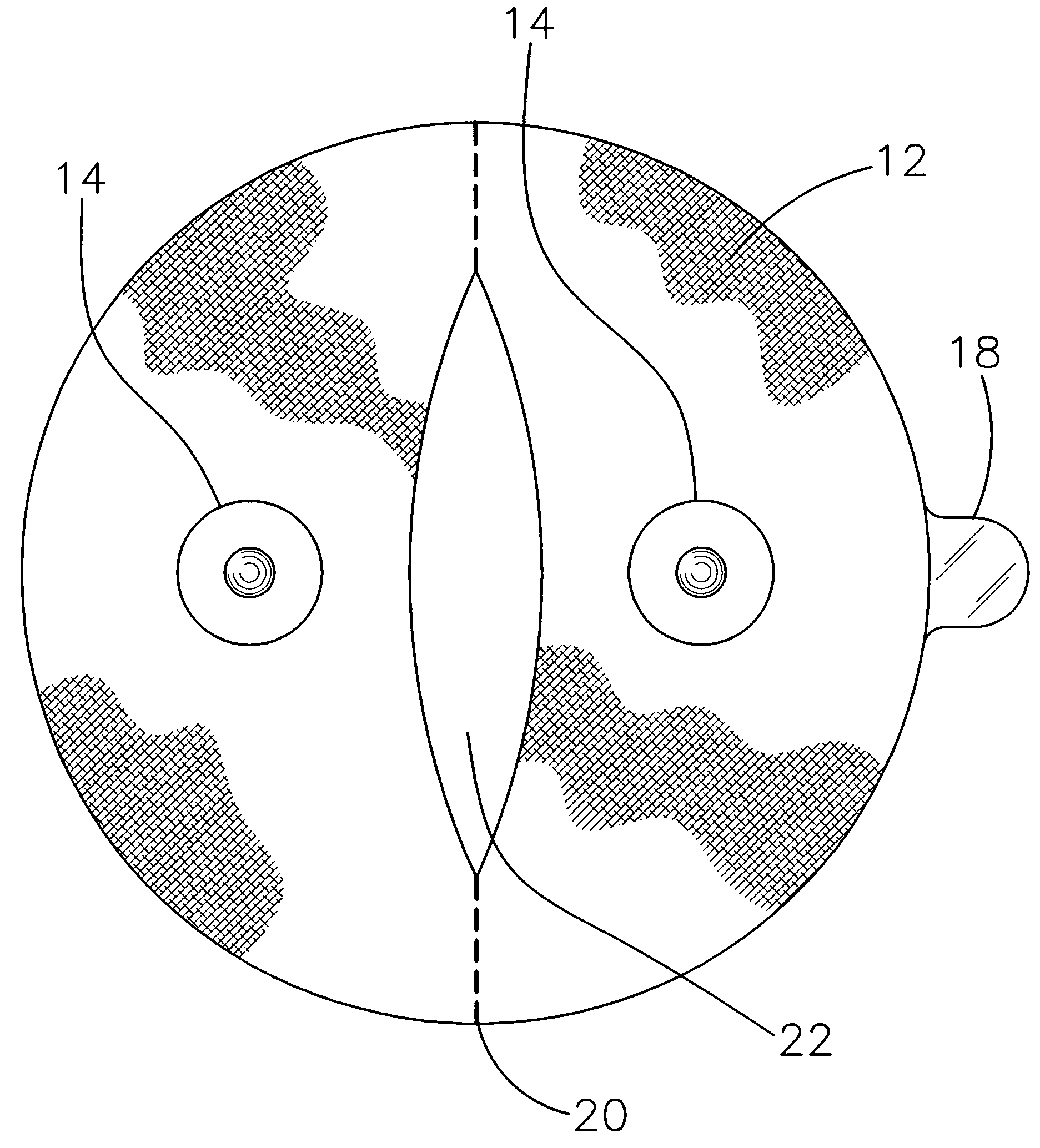
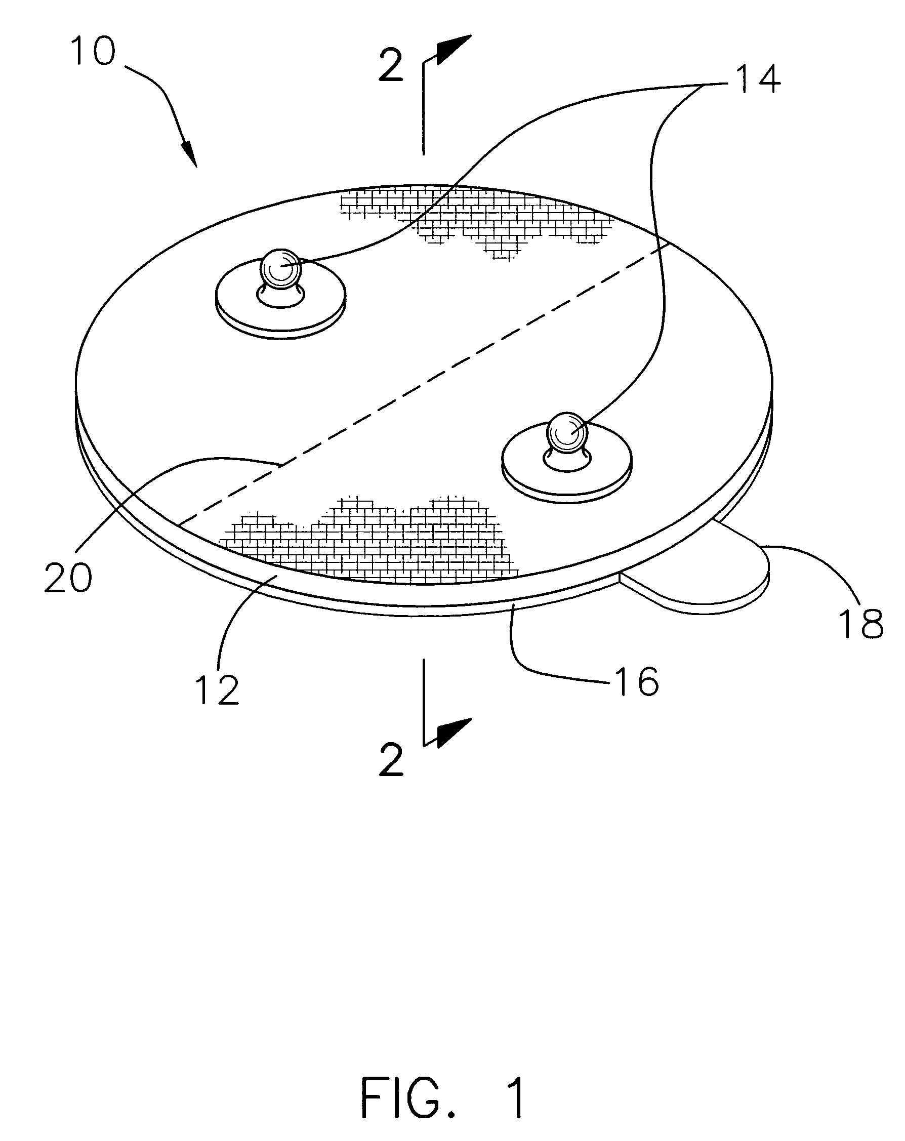
[0036]Referring now to the drawings, and particularly to FIGS. 1–5, a current embodiment of the multiple electrode assembly of the present invention is shown and generally designated by the reference numeral 10.

[0037]In FIG. 1, a new and improved multiple electrode assembly 10 of the present invention for bioelectric monitoring is illustrated and will be described. More particularly, the multiple electrode assembly 10 has a circular body 12 with a diameter of 2¼ inches made of a flexible, nonconducting material such as rubber. Inserted through body 12 are lead attachments 14 made of a conductive material such as metal. Removably attached to the underside of body 12 is peel-off backing 16 with peel tab 18 to facilitate the removal process. Electrical isolation perforation 20, which bisects body 12, also is visible.

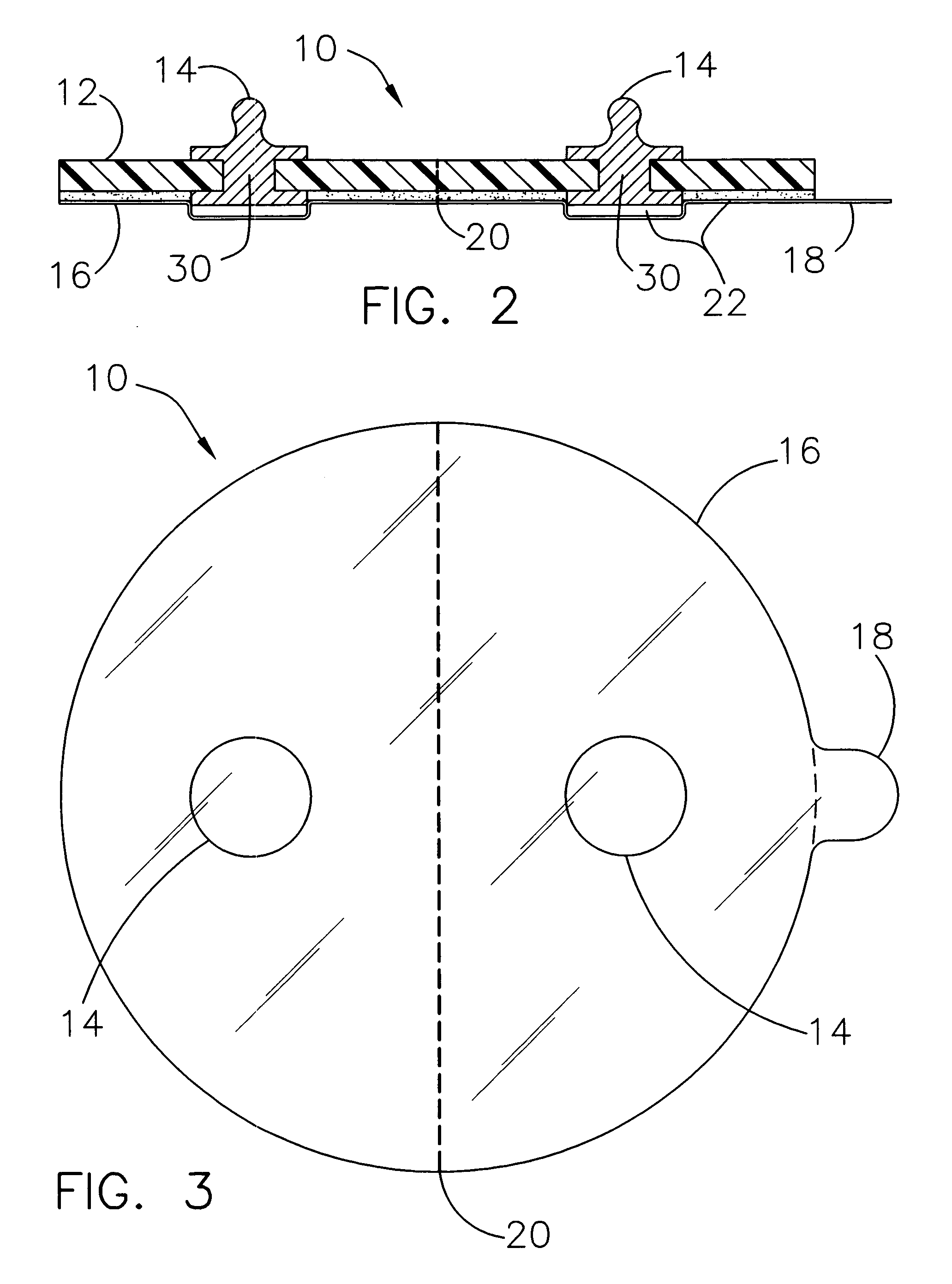
[0038]Moving on to FIG. 2, a new and improved multiple electrode assembly 10 of the present invention for bioelectric monitoring is illustrated and will be described. More ...


PUM


Abstract

Multiple electrode assemblies provide an electrical connection between a patient's body and monitoring equipment. A multiple electrode assembly requires only half as many assemblies as a conventional single electrode assembly to attach a patient to multiple pieces of equipment. Less time is required to attach the patient to the monitoring equipment. There is less patient discomfort since fewer assemblies are attached to the patient. The placement of fewer assemblies also leads to a reduced cost. The assemblies can take on a number of different shapes and lead attachment configurations to accommodate a wide range of monitoring functions.

Description

BACKGROUND OF THE INVENTION[0001]1. Field of the Invention[0002]The present invention relates to a multiple electrode assembly for use in connection with EKG machines. The multiple electrode assembly has particular utility in connection with bioelectric monitoring.[0003]2. Description of the Prior Art[0004]Multiple electrode assemblies are desirable for providing an electrical connection between a patient's body and monitoring equipment such as an EKG machine. A multiple electrode assembly, as opposed to a single electrode assembly, is attractive for a number of reasons. Only half as many assemblies are required to attach a patient to multiple pieces of equipment. This means that less time is required in an emergency situation to attach the patient to the monitoring equipment. There is less patient discomfort since fewer assemblies are attached to the patient. The placement of fewer assemblies also leads to a reduced cost.[0005]The use of adhesive multiple electrode systems is known...

Claims


Application Information

Patent Timeline
IPC IPC(8): A61B5/04
CPCA61B5/04085A61B5/0416A61B5/6833A61B5/282A61B5/274
Inventor BURKS, JONATHAN W.
Owner BURKS JONATHAN W
Why Eureka
Try Eureka