Electromagnetic method and apparatus for the measurement of linear position

a technology of linear position and electric field, applied in the direction of magnets, instruments, magnets, etc., can solve the problems of increasing frequency, low accuracy and resolution of previous methods, and concentrating energy in both transverse and longitudinal directions, and achieve high resolution, high accuracy and resolution, and high accuracy.

Active Publication Date: 2007-05-08
NYCE DAVID S
View PDF7 Cites 25 Cited by
  • Summary
  • Abstract
  • Description
  • Claims
  • Application Information

AI Technical Summary

Benefits of technology

[0015]The main advantages of such a sensing element, in comparison to Prior Art, include: relatively low operating frequency, concentration of electromagnetic energy in a small volume, the independence of electromagnetic parameters upon the electronic circuit parameters, and high sensitivity to the position of the measured object or target.
[0018]The simplicity and inexpensive construction are due to the use of a relatively low operating frequency, which allows the use of printed-circuit techniques and inexpensive electronic components. The high accuracy and resolution are due to the sensing element design: the slow-wave structure-based sensing elements can be fabricated with a temperature-stable dielectric base, contrary to, for example, cavity resonators.
[0019]The present invention teaches an electromagnetic method of measuring the position of a movable object, its speed, direction (velocity), acceleration, or other measurements that require high resolution wherein: an excited electromagnetic wave with a preset distribution of the electric and magnetic components of the electromagnetic field makes it possible to increase the sensitivity and accuracy of measurement, using relatively low frequencies. The method is implemented in an apparatus, for example, a linear position sensor, wherein the structural form of the sensing element and the conductive surface (target) of the movable object are adjusted to allow increased sensitivity and accuracy. In the invention, the sensing element includes at least one section of a coupled slow-wave structure which is sensitive to the position of a movable object or target.

Problems solved by technology

In addition, slowing of the electromagnetic wave leads to concentration of the energy in both the transverse and longitudinal directions.
Previous methods have low accuracy, sensitivity, and resolution at relatively low frequency, increasing only with a substantial increase in the operating frequency.
However, an increase in frequency is accompanied by an increase in electromagnetic losses, such losses limiting the accuracy of the measurement.
It is also generally known that a higher operating frequency can increase the cost of the associated electronic circuitry.
The previous methods therefore require complex and expensive equipment.

Method used


Image

  • Electromagnetic method and apparatus for the measurement of linear position
  • Electromagnetic method and apparatus for the measurement of linear position
  • Electromagnetic method and apparatus for the measurement of linear position

Examples


Embodiment Construction

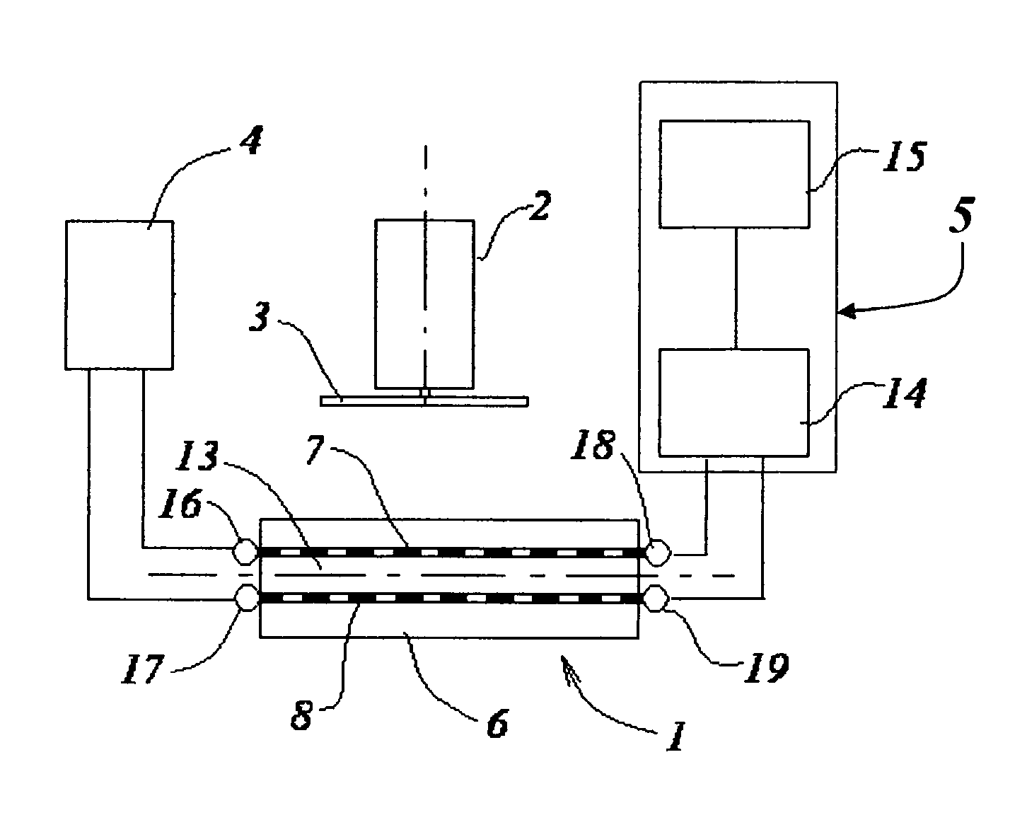
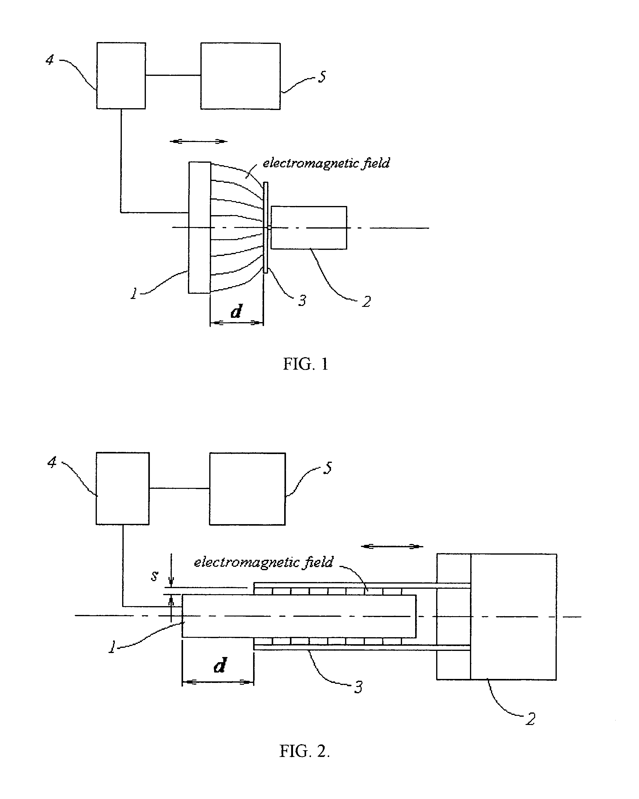
[0036]According to the present invention, a distance, d, between sensing element 1 and a movable object 2 is measured by exciting an alternating electromagnetic field in sensing element 1, and measuring a corresponding electromagnetic parameter of sensing element 1, acted upon by interaction of the electromagnetic field with conductive target 3 mounted on object 2. (FIG. 1 and FIG. 2). The electromagnetic field is excited by an RF or microwave oscillator 4, connected to sensing element 1 and a measuring circuit 5. Currents and charges excited on the conductive surface of target 3 change the electromagnetic parameters. Such an electromagnetic parameter can be measured as a change in the resonant frequency fr of sensing element 1, its impedance Z, phase shift Θ, and other electrical measurements. Changes in these parameters depend on distance d, intensity and configuration of the electromagnetic field extending from sensing element 1 to target 3, and also, the surface conductivity of ...


PUM


Abstract

A method and apparatus are disclosed for monitoring a linear position, such as the distance between a sensing element and a movable object, and / or related parameters, such as displacement, direction, speed, velocity, and / or acceleration. The method utilizes a sensing element and an electrically conductive portion of the movable object, or a conductive target coupled to the movable object. The apparatus includes at least one sensing element formed by a section of a coupled slow-wave structure. The sensing element is connected to an RF or microwave generator, and an electronic circuit that converts at least one electromagnetic parameter of the section of the coupled slow-wave structure into a position reading. Electric and magnetic fields excited in the sensing element are split so that most of the electric energy is concentrated inside of the sensing element, while most of the magnetic energy is concentrated outside of the sensing element. The distance that defines the linear position is measured as a resonant frequency, impedance, phase shift or other electromagnetic parameter.

Description

FIELD OF THE INVENTION[0001]The present invention relates to the measurement of linear position, more specifically, to an electromagnetic method and apparatus for measuring linear position, and related motion parameters. The related motion parameters including displacement, direction, speed, velocity, or acceleration.BACKGROUND OF THE INVENTION[0002]The usefulness of an RF (radio frequency) or microwave electromagnetic field for the purpose of linear position measurement is recognized in Prior Art Such devices can operate with either an RF or microwave excitation. When an electromagnetic field is excited near a movable object, the parameters of the electromagnetic field, such as resonant frequency, phase or amplitude, vary with the change of position of the movable object. The electromagnetic field parameters may be converted into an electronic indication of position, displacement, velocity, or acceleration of the movable object. In particular, the state of the art is shown in U.S. ...

Claims


Application Information

Patent Timeline
Patent Type & Authority Patents(United States)
IPC IPC(8): G01C17/28
CPCG01P3/64G01P15/001G01P15/16G01D5/2291
Inventor PCHELNIKOV, YURIY NIKITICHNYCE, DAVID SCOTT
Owner NYCE DAVID S
Why Eureka
Try Eureka