Metering demand fuel system for gas turbine engines

a gas turbine engine and fuel system technology, applied in the field of fuel systems, can solve the problems of increasing the temperature of the fuel within the fuel tank, not being acceptable in the industry, and using an electric motor instead of the turbine engine to drive the positive displacement pump to meet the fuel demand of the turbine engine, so as to reduce the access pressure and flow

Active Publication Date: 2007-05-15
HAMILTON SUNDSTRAND CORP
View PDF10 Cites 32 Cited by
  • Summary
  • Abstract
  • Description
  • Claims
  • Application Information

AI Technical Summary

Benefits of technology

[0010]Accordingly, the present invention provides a fuel system that eliminates the need for expensive, high accuracy fuel metering valves and reduces access pressure and flow within the fuel system.

Problems solved by technology

As a result, the fuel system utilizes a bypass valve to return the unneeded fuel back to tank, which is greatly inefficient.
Moreover, the returned fuel is hot, which undesirably raises the temperature of the fuel within the fuel tank.
Utilizing an electric motor instead of the turbine engine to drive the positive displacement pump to meet a turbine engine fuel demand is not practical.
In one example, an 80 horse power motor weighing over 100 pounds would be necessary to supply the needed fuel to the turbine engine, which is not acceptable within the industry.

Method used


Image

  • Metering demand fuel system for gas turbine engines
  • Metering demand fuel system for gas turbine engines
  • Metering demand fuel system for gas turbine engines

Examples


Embodiment Construction

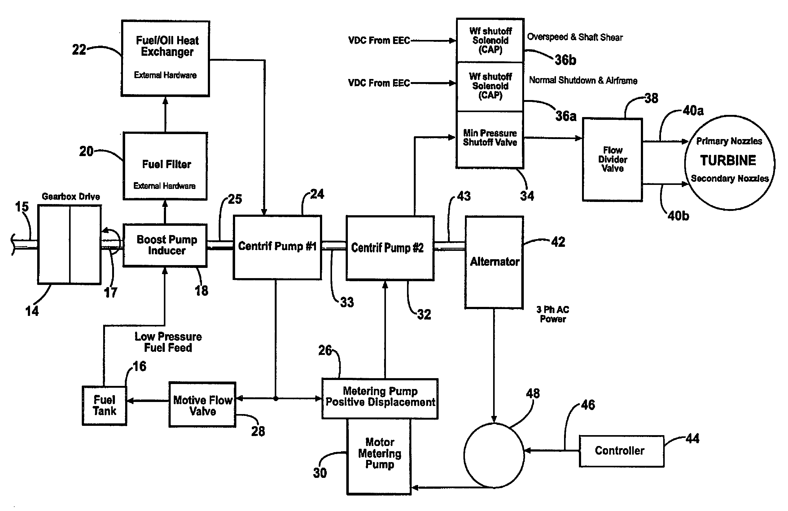
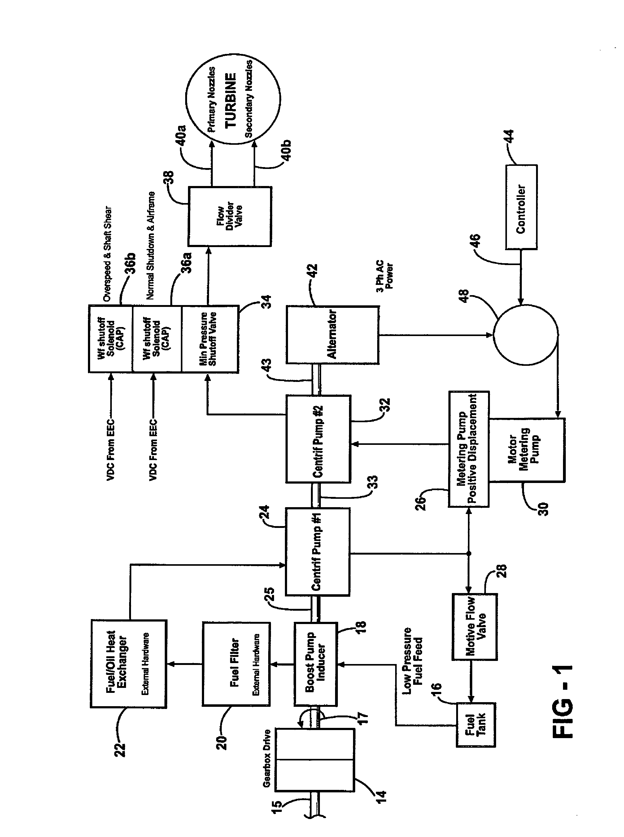
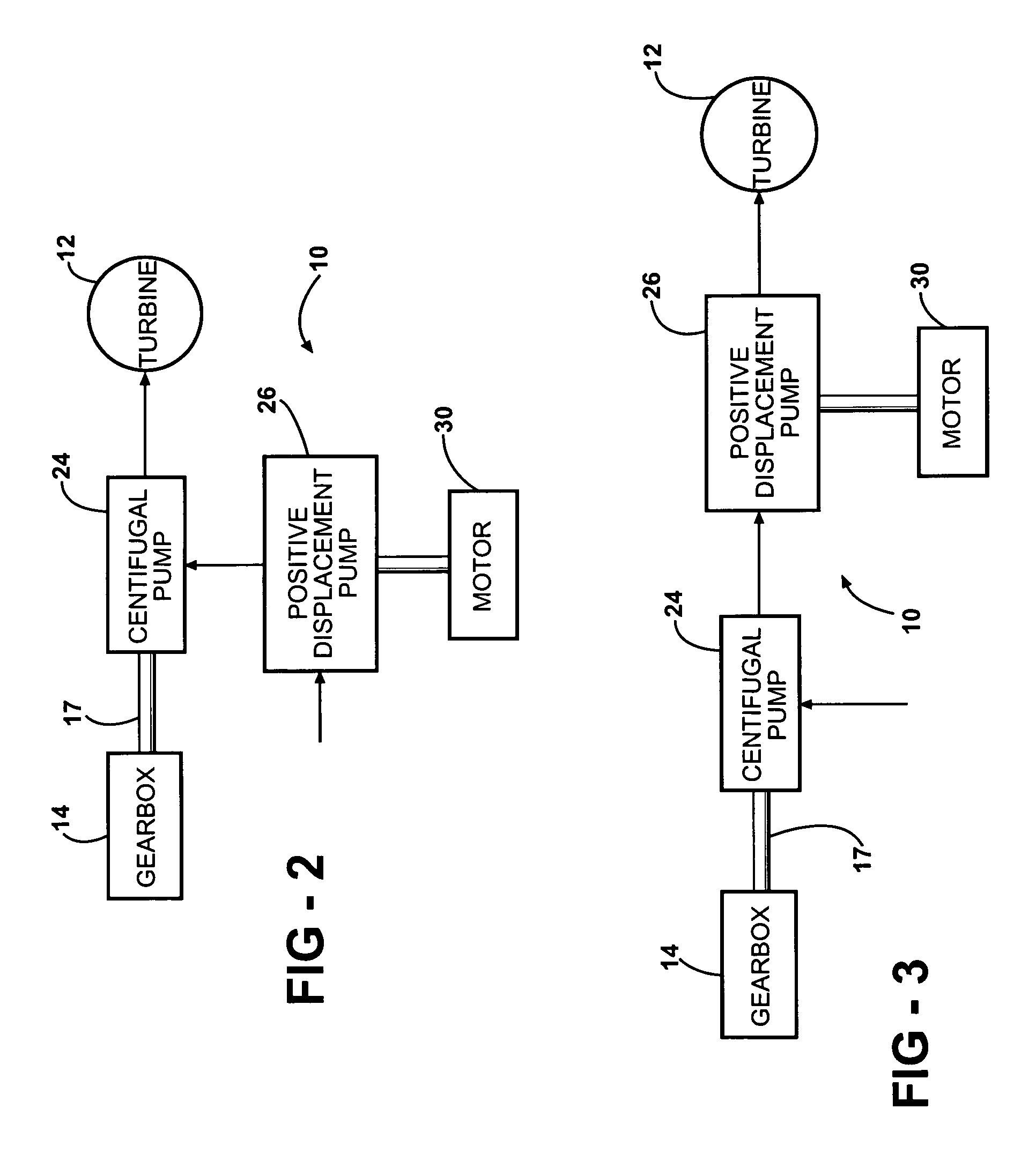
[0015]A schematic of one example of an inventive fuel system 10 is shown in FIG. 1. The fuel system 10 includes a turbine engine 12 that receives fuel from a fuel tank 16. A gearbox 14 is used to drive various components of the fuel system 10 and may be mounted on the turbine engine 12 such that gearbox 14 receives rotational input from the turbine engine 12.

[0016]The fuel system 10 only illustrates portions of an example fuel system for clarity. The components depicted should in no way be interpreted as limiting the inventive pump arrangement. The example fuel system 10 shown may be suitable for small engine applications such as those used for business jets. Large engine and other small engine applications may have different or additional components.

[0017]The gearbox 14 drives a boost pump inducer 18 through a shaft 17. The boost pump inducer 18 draws fuel from the fuel tank 16 and delivers the fuel to a fuel filter 20 and heat exchanger 22, which removes heat from the fuel.

[0018]A...


PUM


Abstract

A fuel system includes a turbine engine, and an electric motor that are independently drivable relative to one another. The electric motor has a speed that is selectively controlled based upon a desired fuel flow. A centrifugal pump is driven by the turbine engine. The centrifugal pump provides a desired fuel pressure for the fuel system. A positive displacement pump is driven by the electric motor The positive displacement pump is in fluid communication with the centrifugal pump, for example in a series arrangement. The positive displacement pump meters a desired volume in response to the speed of the second drive assembly.

Description

BACKGROUND OF THE INVENTION[0001]This invention relates to a fuel system for delivering fuel to gas turbine engines.[0002]Prior art fuel systems include a large positive displacement pump driven by a turbine engine through a gearbox. To achieve the desired fuel volumes and pressures for the demands of the turbine engine, the positive displacement pump is specifically oversized for peak demand. As a result, the fuel system utilizes a bypass valve to return the unneeded fuel back to tank, which is greatly inefficient. Moreover, the returned fuel is hot, which undesirably raises the temperature of the fuel within the fuel tank. Excess pressure that is generated must be relieved using a pressure regulator to mitigate any potential burst or over pressure conditions.[0003]Prior art fuel systems employ precision metering valves to regulate the flow rate through the fuel system to meet the turbine engine fuel demand. The metering valves have tight tolerances and any contamination present wi...

Claims


Application Information

Patent Timeline
Patent Type & Authority Patents(United States)
IPC IPC(8): F02C9/28
CPCF02C7/236F02C9/30
Inventor PARSONS, DOUGLAS A.
Owner HAMILTON SUNDSTRAND CORP
Why Eureka
Try Eureka