Slope predictive control and digital PID control

a predictive control and digital technology, applied in ventilation systems, heating types, domestic cooling apparatuses, etc., can solve problems such as inefficiency of pressure-dependent vav control systems, airflow into other rooms affected, and temperature control loops to “fight"

Inactive Publication Date: 2007-05-15
AUTOMATED LOGIC CORP
View PDF21 Cites 61 Cited by
  • Summary
  • Abstract
  • Description
  • Claims
  • Application Information

AI Technical Summary

Benefits of technology

[0016]As a result of using the predictive control scheme, the flow control loop minimizes the movement of the flow control damper and increases the life of the damper operator. When compared to conventional control systems, the predictive control loop decreases the movement of the airflow control damper substantially.

Problems solved by technology

One drawback to pressure dependent VAV temperature control systems is that a central Air Handling Unit supplies air to many VAV boxes and when the damper of one VAV box is opened or closed to adjust the temperature in its associated room, the airflow into the other rooms will be affected.
This can cause the temperature control loops to “fight” each other, as a temperature change in one room will likely cause a flow change in the other rooms.
Accordingly, pressure dependent VAV control systems can be inefficient for controlling a heating, ventilation and air conditioning (HVAC) system within a sufficiently large building having multiple rooms.
However, pressure independent VAV control systems also have associated drawbacks.
For example, one problem with a typical flow control loop in pressure independent systems is that it is very difficult to provide stable airflow into the room without excessively modulating the damper.
The excessive modulation of a damper eventually causes the damper to fail and require replacement.
System downtime and maintenance expenses incurred due to failed dampers are common problems in the temperature control industry.
Another drawback associated with a typical flow control loop in a pressure independent VAV control system is the effect of turbulent flow in the air ducts of the system.
Electronic sensors can accurately measure instantaneous flow in the air ducts, but the turbulent flow can cause the resulting signals to be very noisy.
Yet another problem associated with the typical flow control loop of a pressure independent VAV control system results from the inherent non-linear response curve of each damper within each VAV box and from the fact that the electric motors which move these dampers can be damaged by repeated short pulses of current which attempt to move the damper a very short distance.
If the pulse is short enough, the motor may not build up enough torque to overcome the static friction needed to move at all.
If no additional protection is taken, the control system can pulse the motor indefinitely and damage the motor.
If less than a one second movement was needed to bring the flow to setpoint, this one second minimum run time can drive the damper too far and result in a flow reading on the other side of the setpoint.
Without additional protection, this would result in the controller giving a short pulse to the damper to move it in the other direction.
The minimum run time would again cause the damper to overshoot the setpoint, and the system could cycle indefinitely, causing excessive wear on the damper and the motor.
However, a wide deadband produces inaccurate control at the low and high end of the damper response curve.
The low end of the damper response curve is particularly problematic, because of indoor air quality concerns.
Therefore, a low flow rate and a very wide deadband may cause the airflow control loop to maintain a flow rate that is below the minimum ventilation flow, and cause a problem for indoor air quality.
While the aforementioned problems affect the flow control loop in pressure independent VAV systems, the temperature control loop in such system may also suffer from problems that affect its performance.
Finding the correct gains is often a difficult process (called “tuning” the control system) and the result is a compromise between stability and accuracy.

Method used


Image

  • Slope predictive control and digital PID control
  • Slope predictive control and digital PID control
  • Slope predictive control and digital PID control

Examples


Embodiment Construction

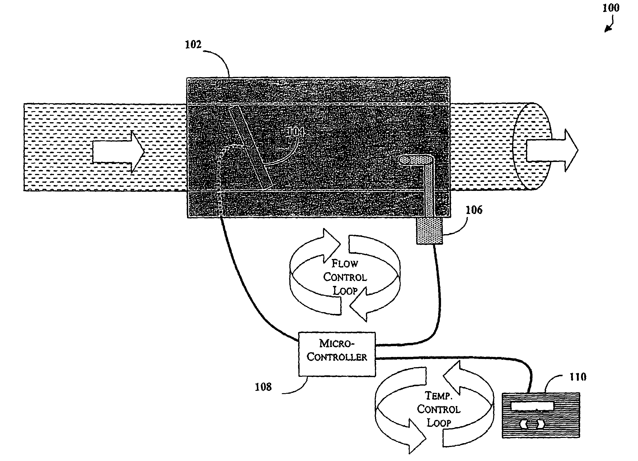
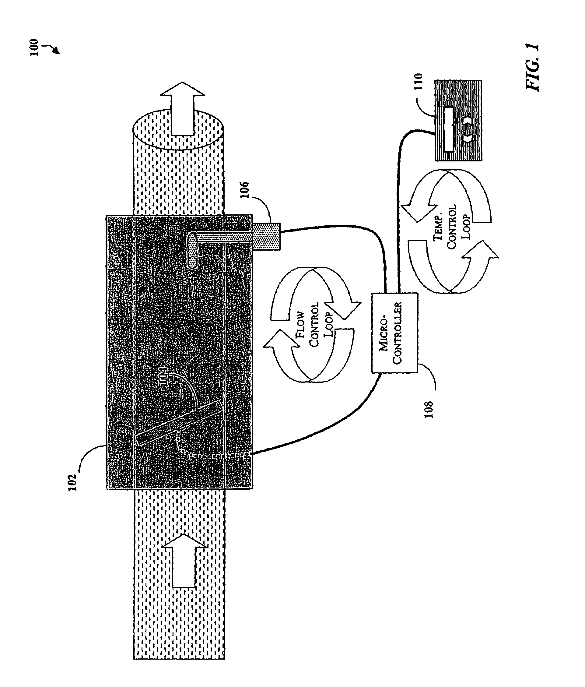
[0021]In one embodiment, the present invention provides flow and temperature control loops to accomplish a Variable Air Volume (VAV) temperature control algorithm in a manner that addresses the problems encountered in the control of prior art pressure independent VAV control systems.

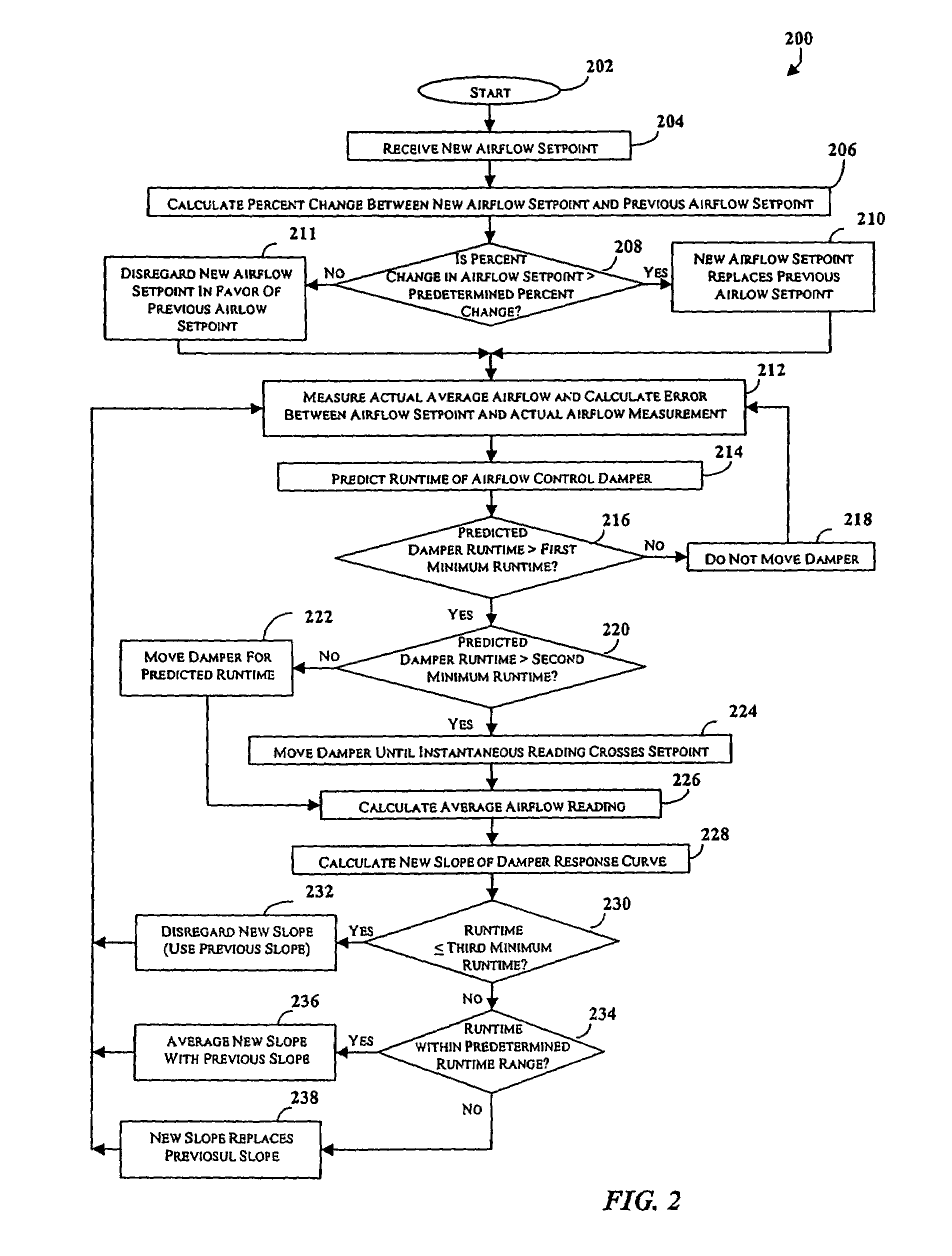
[0022]To address the problem of noisy instantaneous signals representing flow measurements, the present invention averages the instantaneous flow measurements over a period of time. The averaging technique serves to settle and eliminate a significant amount of the noise in the instantaneous flow measurement signals, and provides a better measurement of the average airflow into the room. Normally, when flow measurements are averaged over time, delay is introduced into the control loop. This delay causes the flow controls to overshoot the setpoint because by the time the averaging of the measurements is complete, the airflow control damper has moved past the desired position. The present invention avoids t...


PUM


Abstract

The present invention provides an airflow control loop that uses averaged airflow measurements without the problems that are normally encountered with averaging measurements, such as the delay introduced into the airflow control loop. This is accomplished, in the present invention, through a predictive control scheme. The predictive control scheme of the airflow control loop calculates the damper sensitivity, calculates the damper runtime needed to achieve setpoint, and then runs the damper for the determined period of time. In addition to the unique airflow control loop used to maintain the constant airflow into the room, the present invention also implements a digital form of proportional, integral, and derivative (PID) control to maintain the room temperature. The digital form of PID control uses non-linear gains which vary according to how far the measured temperature is from setpoint.

Description

RELATED APPLICATIONS[0001]The present application is a continuation of U.S. application Ser. No. 10 / 425,136, filed Apr. 28, 2003 now U.S. Pat. No. 6,715,690, which is a continuation of U.S. application Ser. No. 09 / 850,422, filed May 7, 2001, now U.S. Pat. No. 6,554,198, both of which are incorporated herein in their entirety by reference.TECHNICAL FIELD[0002]The present invention relates generally to control systems. More particularly, the present invention relates to Variable Air Volume (VAV) temperature control systems.BACKGROUND OF THE INVENTION[0003]Variable Air Volume (VAV) temperature control systems control the temperature within a room by modulating the amount of cool (or warm) air that is blown into the room by the heating and air conditioning system. A pressure dependent VAV temperature control system uses a temperature control loop to accomplish a temperature control algorithm. The temperature control loop attempts to maintain a room temperature setpoint by using readings...

Claims


Application Information

Patent Timeline
Patent Type & Authority Patents(United States)
IPC IPC(8): F24F7/00F24F11/00F24F13/08G05D7/06G05D23/19
CPCF24F11/006F24F11/022F24F13/08G05D7/0635G05D23/1904F24F11/30F24F11/62F24F11/72
Inventor HULL, GERRY GLANCYTOM, STEVEN TREECESAAR, RAYNOLD LEE
Owner AUTOMATED LOGIC CORP
Why Eureka
Try Eureka