Illuminated signage employing light emitting diodes

a technology of light-emitting diodes and illumination signage, which is applied in the direction of identification means, contact members penetrating/cutting insulation/cable strands, lighting support devices, etc., can solve the problems of high-voltage applications, high-voltage applications, and high-voltage applications, so as to avoid soldering connections and reduce the number of parts

Inactive Publication Date: 2007-05-15
GE LIGHTING SOLUTIONS LLC
View PDF69 Cites 125 Cited by
  • Summary
  • Abstract
  • Description
  • Claims
  • Application Information

AI Technical Summary

Benefits of technology

[0016]One advantage of the present invention resides in providing a channel lettering having a reduced number of parts compared with past systems.
[0017]Another advantage of the present invention resides in the use of parallel interconnection of the LEDs which reduces the likelihood that a failed LED will adversely affect performance of other LEDs on the same electrical circuit.
[0018]Another advantage of the present invention resides in the locating of the conditioning electronics away from the channel lettering, e.g. in a secure and weatherproofed interior location.
[0019]Another advantage of the present invention is the avoidance of soldering connections in the flexible LED light engine.
[0020]Yet another advantage of the present invention is that it allows for coupling in the electrical power anywhere along the flexible LED light engine.
[0021]Still yet another advantage of the present invention resides in its modular nature which allows part or all of a channel lettering to be constructed on-site in a customized manner.

Problems solved by technology

Neon systems are very fragile and, therefore, tend to fail and / or break during manufacture, shipping or installation.
High voltage applications have been associated with deaths by electrocution and building damage due to fire.
For example, the conventional LED channel lettering systems offer only limited flexibility.
More specifically, the LEDs cannot be easily set into a desired shape involving significant curves or bends (e.g., wrapped around a pole or in a very small radius (<3 inches).
Furthermore, the LEDs cannot be easily moved from one lighting application to another.

Method used


Image

  • Illuminated signage employing light emitting diodes
  • Illuminated signage employing light emitting diodes
  • Illuminated signage employing light emitting diodes

Examples


Embodiment Construction

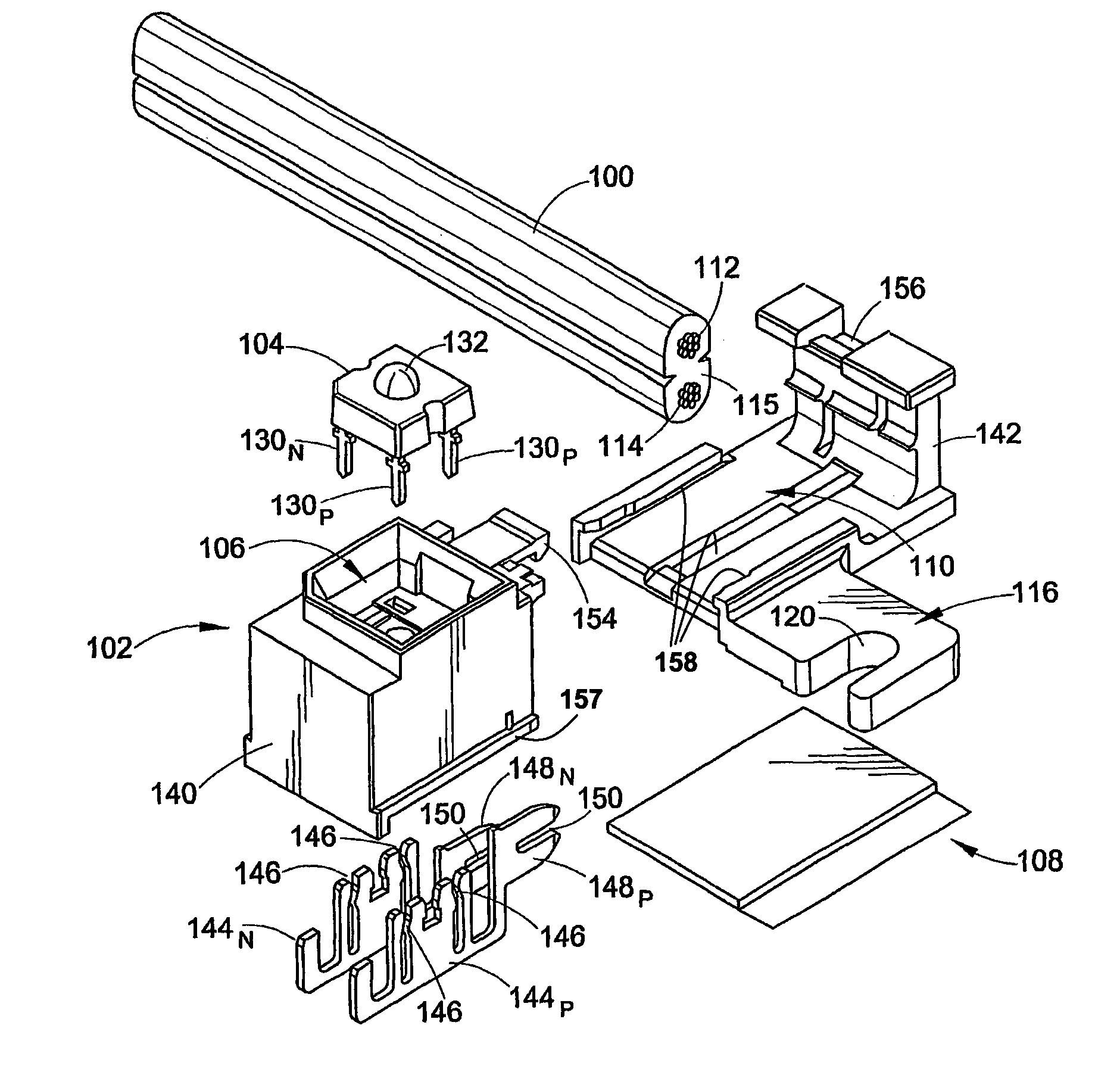
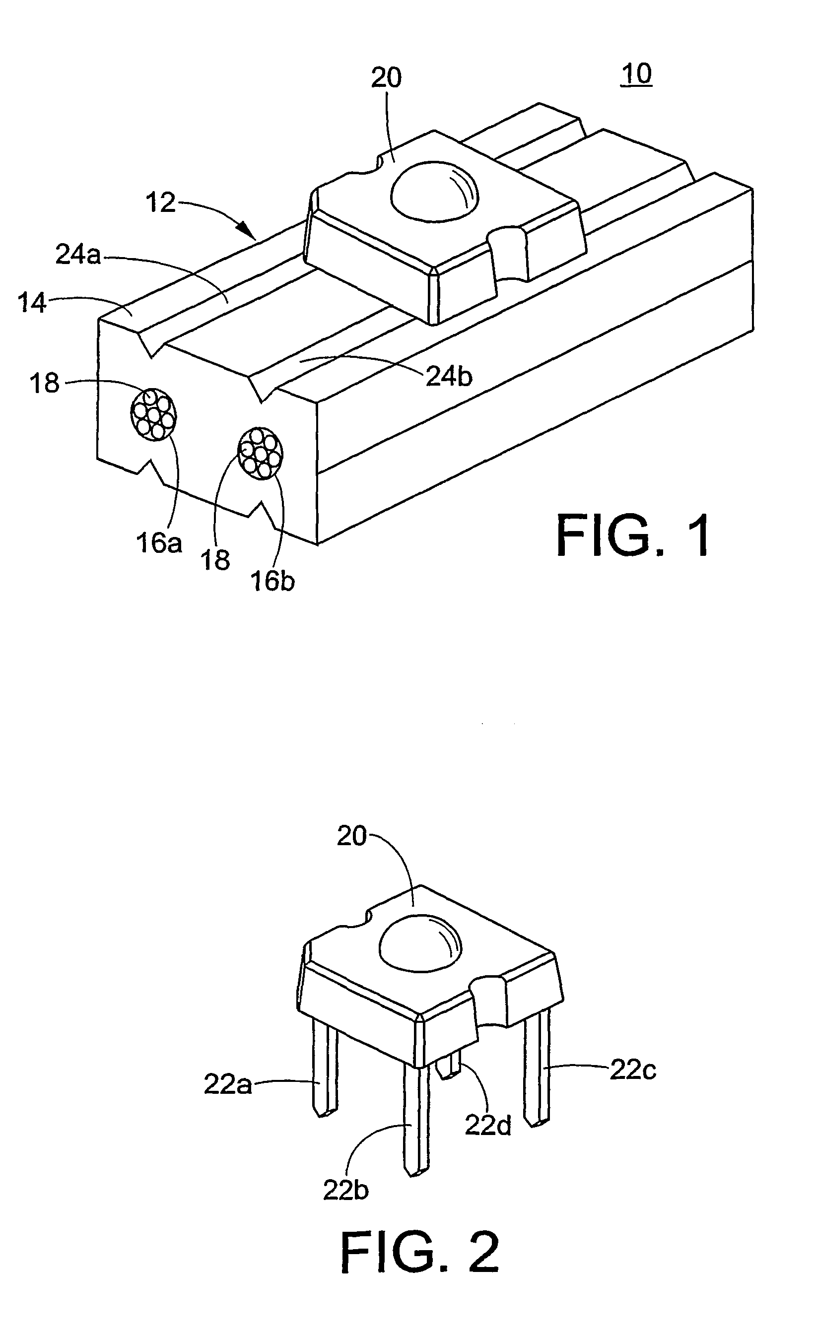
[0040]With reference to FIG. 1, a light emitting diode (LED) light engine 10 includes a flexible electrical conductor 12 surrounded by a flexible, electrically insulating covering 14. More specifically, the conductor 12 includes a plurality of substantially parallel conductive elements 16, each of which is electrically insulated by the insulating covering 14. In the preferred embodiment, the insulating covering 14 includes rubber, PVC, silicone, and / or EPDM. However, other material are also contemplated.

[0041]Preferably, the conductor 12 includes two conductive elements 16a, 16b. Furthermore, each of the conductive elements 16a, 16b is preferably sized to be about 14 gauge. Additionally, each of the conductive elements 16a, 16b is preferably stranded and includes a plurality of strands 18 (e.g., seven strands).

[0042]The LED light engine 10 also includes an LED 20, which electrically contacts the conductive elements 16 and is mechanically secured to the insulating covering 14. More s...


PUM


Abstract

An illuminated sign (88) includes a flexible electrical power cord (100) including first and second parallel conductors (112, 114) surroundingly contained within an insulating sheath defining a constant separation distance between the parallel conductors (112, 114). A plurality of light emitting diode (LED) devices (102) are affixed to the cord (100). Each LED device (102) includes an LED (104) having a positive lead (130p) electrically communicating with the first parallel conductor (112) and a negative lead (130p) electrically communicating with the second parallel conductor (114). A stencil (92) defines a selected shape, and the electrical cord (100) is arranged on the stencil (92). Power conditioning electronics (210, 220) disposed away from the stencil (92) electrically communicate with the first and second parallel conductors (112, 114) of the electrical power cord (100). The power conditioning electronics (210, 220) power the LED devices (102) via the parallel conductors (112, 114).

Description

[0001]This application claims priority from U.S. Non-provisional patent application Ser. No. 09 / 866,581 filed on May 25, 2001 now U.S. Pat. No. 6,660,935.BACKGROUND OF THE INVENTION[0002]Channel letters are known to those skilled in the art of making commercial signs as the most attractive and expensive form of sign lettering. Briefly, channel letters usually include a plastic or metal backing having the shape of the letter to be formed. Metal channel siding, frequently formed of aluminum with a painted or otherwise finished interior and exterior surface, is attached to and sealed to the letter backing, giving depth to the letter to be formed. Electrical lighting fixtures, such as neon tubing and mounting brackets, are attached to the letter backing. Typically, a colored, translucent plastic letter face is attached to the front edge portion of the channel side material.[0003]As discussed above, neon lighting is typically incorporated into channel lettering systems. Neon systems are ...

Claims


Application Information

Patent Timeline
Patent Type & Authority Patents(United States)
IPC IPC(8): F21V21/00G09F13/20F21V21/002G09F9/33G09F13/04H01L33/00H01L33/44H01L33/58
CPCG09F9/33G09F13/0404G09F13/22G09F13/0413F21V21/002F21Y2101/02F21S4/003Y10S362/80Y10S362/812F21S4/20F21Y2115/10
Inventor SOUTHARD, PAULAANEGOLA, SRINATH K.PETROSKI, JAMES T.BOHLER, CHRISTOPHER
Owner GE LIGHTING SOLUTIONS LLC
Why Eureka
Try Eureka