Balloon cones and waists thinning methodology

a balloon and cone technology, applied in balloon catheters, surgery, ear treatment, etc., can solve the problems of affecting the difficulty of tracking, crossing and recrossing lesions, and the damage of the blood vessel, so as to reduce the wall thickness of the cone and the waist portion, and improve the strength of the balloon wall

Inactive Publication Date: 2007-05-15
BOSTON SCI SCIMED INC
View PDF36 Cites 14 Cited by
  • Summary
  • Abstract
  • Description
  • Claims
  • Application Information

AI Technical Summary

Benefits of technology

[0018]There remains a need to continue to improve balloon wall strengths while simultaneously reducing their wall thickness. The present invention addresses these needs by reducing the wall thickness of cone and waist portions. The resulting balloon is smaller in size for easier insertion into the body lumen.

Problems solved by technology

The thicker cone walls contribute to the overall thickness of the catheter, making tracking, crossing and recrossing of lesions more difficult.
Further, thick cones interfere with refolding of the balloon on deflation so that the deflated balloon can only be further inserted or withdrawn with difficulty, occasionally even damaging the blood vessel.

Method used


Image

  • Balloon cones and waists thinning methodology
  • Balloon cones and waists thinning methodology
  • Balloon cones and waists thinning methodology

Examples


example 1

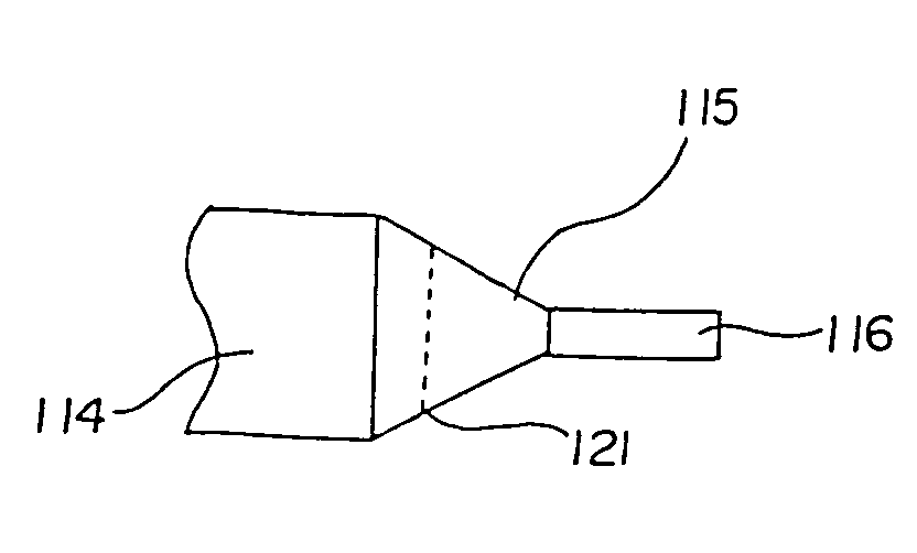
[0082]Coextruded tubing (inner layer Pebax 7233, outer layer Pebax 4033) was ground in accordance with the present invention and formed into a balloon using the method described immediately above. Measurements were made for balloons formed from tubes with a grind transition 121 half way along the distal cone 115 (lower cone transition) shown schematically in FIG. 5a and tubes with a grind transition 121 at the distal cone 115 body 114 interface (upper cone transition) shown schematically in FIG. 5b. The wall thickness of the balloon was measured in the waist 116, half way along the cone and in the body portion 114 of the balloon. For the sake of comparison, measurements were made on a balloon formed from an unground tube as well (non-grind). The measurements were repeated on balloons formed from four separate tubes. Reported below in Table 1 are the measured single wall thicknesses in inches for samples 1–4. The properties of the initial tubes prior to blowing are reported in Table ...

example 2

[0086]Polybutyleneteraphthalate (PBT) tubing was ground in accordance with the present invention and formed into a balloon using the method described above. The wall thickness of the balloon was measured in the waist, one third of the way along the cone, two thirds of the way along the cone and in the body portion of the balloon. As shown schematically in FIGS. 6a and 6b, measurements were made for balloons formed from tubes with a grind transition 121 two thirds of the way along the distal cone 115 and tubes with a grind transition 121 at the distal cone 115—body 114 interface (upper cone transition). For the sake of comparison, measurements were made on a balloon formed from an unground tube as well (non-grind). The measurements were repeated on four separate tubes. Reported below in Table 3a are the measured single wall thicknesses in inches.

[0087]Measurements were also made on PBT balloons with proximal cones ground as described above and reported below in Table 3b.

[0088]The pro...

example 3

[0093]Pebax 7233 tubing was ground in accordance with the present invention and formed into a balloon using the method described above. The wall thickness of the balloon was measured in the waist, one third of the way along the cone, two thirds of the way along the cone and in the body portion of the balloon. Measurement were made for balloons formed from tubes with a 30% wall grind and a 40% wall grind. As shown schematically in FIG. 7, the grind transition 121 was ⅔ of the way along the distal cone 115. For the sake of comparison, measurements were made on a balloon formed from an unground tube as well (non-grind). The measurements were repeated on four separate tubes. Reported below in Table 5 are the measured single wall thicknesses in inches.

[0094]The properties of the initial tubes are reported in Table 6.

[0095]

TABLE 5DistalQuantum Sample × 10−3 in×10−3 inNongrind1234Avg.Waist3.703.853.703.453.68⅓ cone2.102.402.502.452.36⅔ cone1.001.351.251.301.23body0.750.850.850.750.8024% wa...


PUM

PropertyMeasurementUnit
thicknessesaaaaaaaaaa
Tgaaaaaaaaaa
pressureaaaaaaaaaa

Abstract

Medical balloons and balloon preforms are made by methods which include the step of selectively removing material from the proximal and / or distal ends of a segment. In the case of a thermoplastic material characterized by one or more glass transition temperatures, the segment may optionally be maintained at a temperature below the glass transition temperature of the segment during the material removal step.

Description

CROSS-REFERENCE TO RELATED APPLICATIONS[0001]This application is a Divisional application of U.S. application Ser. No. 09 / 401,618 filed Sept. 22, 1999 now U.S. Pat. No. 6,193,738 which is a Continuation-in-part application of application Ser. No. 09 / 076,252 filed May 11, 1998 and issued as U.S. Pat. No. 6,024,752, the contents of both of which are hereby incorporated by reference.BACKGROUND OF THE INVENTION[0002]The present invention relates to a method for making balloons for catheters used in medical dilatation procedures.[0003]Balloon catheters are being used extensively in procedures related to the treatment of blood vessels. For example, arterial stenosis is commonly treated by angioplasty procedures which involve inserting balloon catheters into specific arteries. Balloon catheters have also been found useful in procedures involving dilation of body cavities.[0004]The most widely used form of angioplasty makes use of a dilatation catheter which has an inflatable balloon at its...

Claims


Application Information

Patent Timeline
Patent Type & Authority Patents(United States)
IPC IPC(8): A61M29/00A61F11/00A61F2/958A61M25/00A61M25/16B29C49/00B29C49/02B29C49/04B29C49/10B29C49/14
CPCA61M25/10A61M25/1029B29C49/0073B29C49/02B29C49/14A61M25/1002A61M2025/1031B29B2911/14593B29B2911/14653B29B2911/14713B29B2911/14793B29B2911/14826B29C49/04B29C49/10B29C2049/0089B29C2049/021B29C2791/001B29K2105/258B29L2022/022B29L2031/7542B29C2949/082B29C2949/0841B29C2949/0846B29C2949/0811B29C2949/0829B29C2949/08B29C49/071
Inventor TOMASCHKO, DANIEL KEITHHORN, DANIEL JAMESZHANG, XIAO KANGLEE, NAO PAO
Owner BOSTON SCI SCIMED INC
Why Eureka
Try Eureka