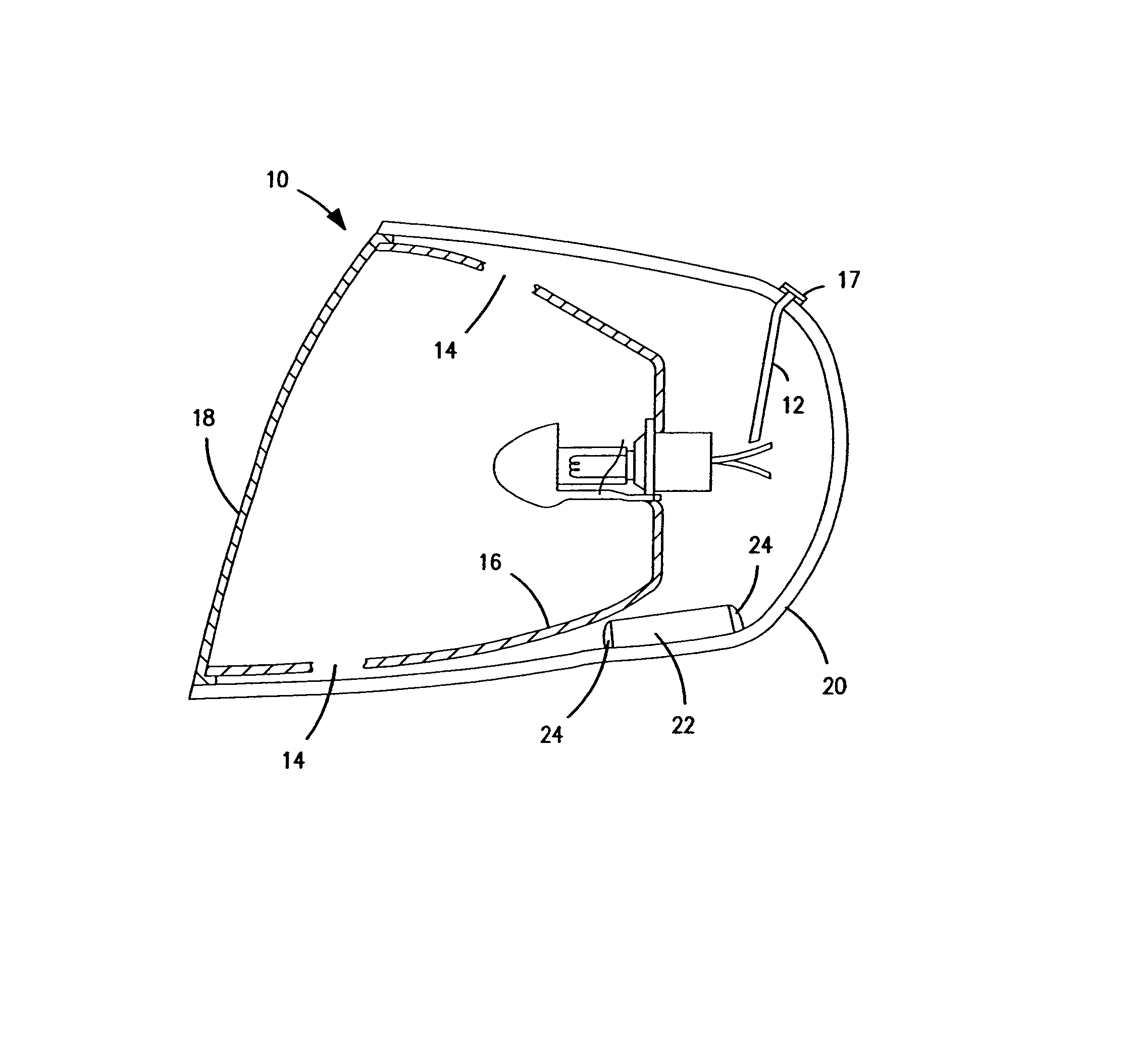
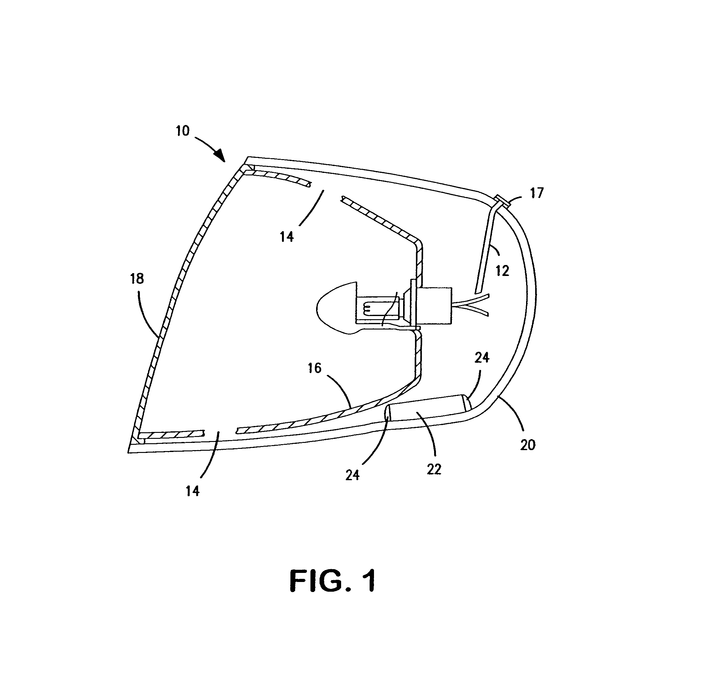
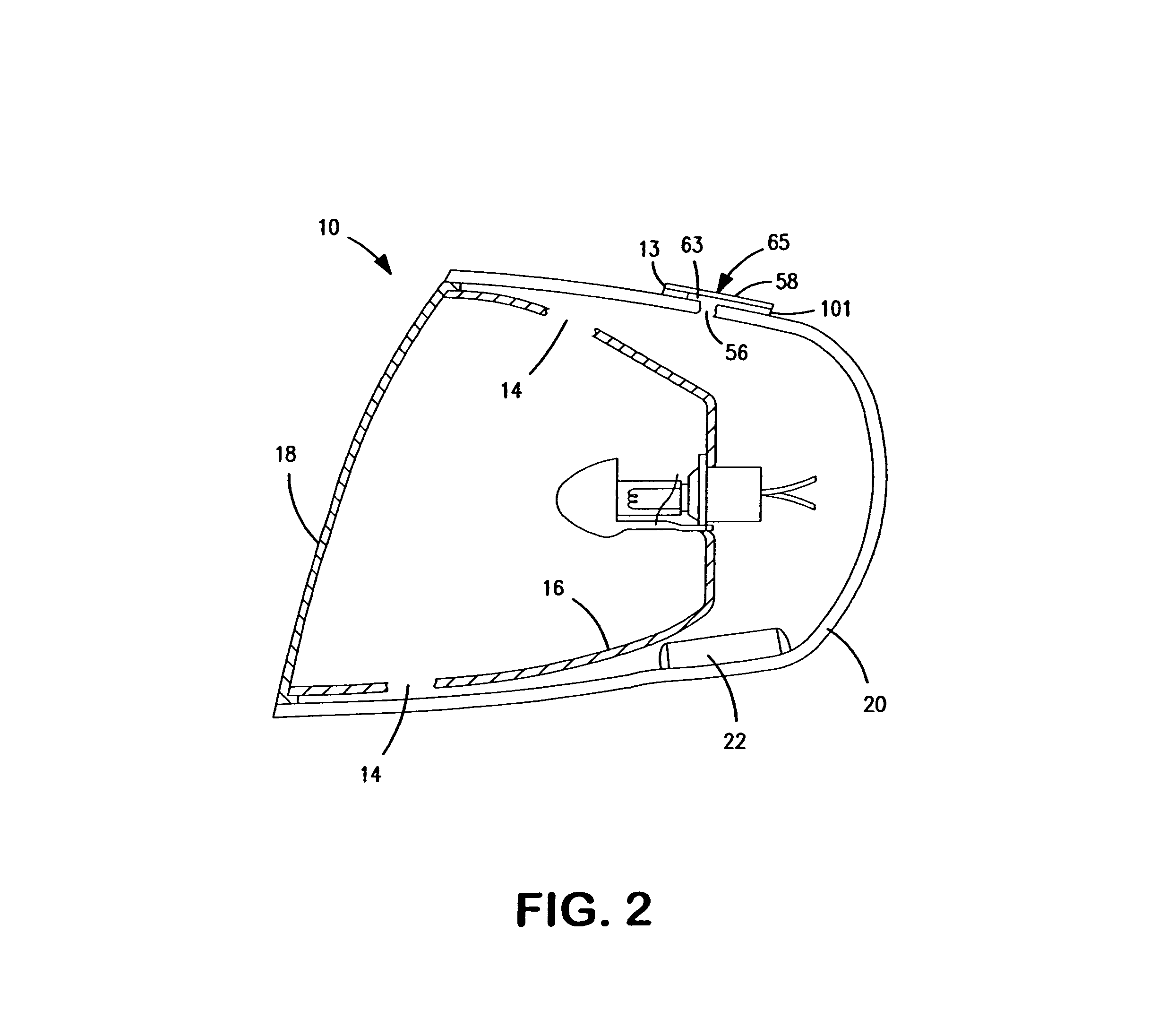
Venting system for minimizing condensation in a lighting assembly

a technology for lighting assemblies and ventilation systems, which is applied in the direction of lighting and heating equipment, transportation and packaging, separation processes, etc., can solve the problems of reducing affecting the service life of lighting assemblies, etc., to achieve the effect of reducing condensation, high capacity and high capacity

Active Publication Date: 2007-05-15
WL GORE & ASSOC INC
View PDF18 Cites 14 Cited by
  • Summary
  • Abstract
  • Description
  • Claims
  • Application Information

AI Technical Summary

Problems solved by technology

Excessive moisture causes damage within many lighting assemblies.
For instance, electrical and electronic items may be ruined due to excessive moisture within a lamp enclosure.
Examples of lighting assemblies which are subject to undesirable moisture include, for example, automotive headlamp units and other outdoor lighting assemblies where on / off cycling of a lamp within the enclosure results in moisture build-up.
The problem of moisture build up within lamp enclosures is particularly acute in automotive lamps.
However, thermal cycling due to bulb operation, changes in the environment and vehicle operation can cause moisture to condense on the interior of the housing and inhibit light output from the lamp.
Moreover, components within a lamp may be damaged by such condensation.
However, it can be very difficult to provide sufficient airflow to reduce moisture.
Moreover, attempts to increase the vent opening sizes can exacerbate problems such as contamination, etc.
However, vent systems that provide a means of increasing airflow through the lamp housing often have a negative effect on lamp performance.
Specifically, these venting systems often create an opportunity for foreign materials and liquid water to enter the vehicle lighting system.
Under certain conditions, particularly in cold, damp weather, desiccant regeneration can be problematic.
However, it has proven difficult to provide enough desiccant to meet the design life of most enclosures because significant amounts of moisture are present in the lamp when assembled or enter the headlamp through the venting system by moisture diffusion from the outside environment and during each cycle that the head lamp is energized and de-energized.

Method used


Image

  • Venting system for minimizing condensation in a lighting assembly
  • Venting system for minimizing condensation in a lighting assembly
  • Venting system for minimizing condensation in a lighting assembly

Examples


example 1

[0060]A lamp housing according to the present invention was produced using the housing of a model year 2004 Saturn Ion2. Both adhesive vents were removed. The original housing included two vents, one inboard and one outboard. The out board vent hole was sealed Dow Corning RTV 832.

[0061]A diffusion tube was installed through the inboard vent hole. A 100 mm long, 1.6 mm OD, 0.75 mm ID Stainless Steel tube was sealed into the inboard vent hole using RTV 832. A 6.3 mm tall Delrin vent stand off, having a 12.7 mm OD and 7.6 mm ID was attached over the top of the tube using the RTV 832. An OLEOGARD® adhesive vent manufactured by W.L. Gore & Associates of Elkton, Md., part number VE0004WAG was placed on top of the standoff to prevent contamination or clogging of the diffusion tube.

[0062]A high capacity, nonregenerating desiccant was placed in a container and installed in the housing. A ten gram mixture of 44% MgCl2 and 56% MgO was prepared and immediately placed into an 8″ ePTFE tube. The ...

example 2

[0064]A second lamp housing according to the present invention was produced from a 2002 Volvo HID headlamp. All original vents were removed and the holes were sealed with RTV 832.

[0065]A moisture reducing device was installed in the housing. The device consisted of a stamped stainless steel cup (20 mm OD×6.5 mm height) with a 0.5 mm vent hole in the bottom, manufactured by Auto-Form, Inc., Waterbury, Conn. A stainless steel tube (0.75 mm ID×1.5 mm OD×125 mm L) was soldered into the bottom of the cup. The cup was filled with about 0.600 grams (±0.005 g) of Type B silica desiccant manufactured by Kaltron Inc. (Kaltron / Pettibone) of Bensenville, Ill., part number Sil 66300. To contain the desiccant, the cup was covered by a silicone rubber imbibed ePTFE Membrane prepared in the following manner:

[0066]A roll of tensilized polytetrafluoroethylene (PTFE) tape, manufacture by DeWal Industries of Sanderstown, R.I., part number 220T, that is approximately 20 cm wide is placed on the payoff o...

example 3

[0070]A housing was assembled using a modified enclosure from a model year 2000 Chevy Silverado in which all original housing vents were sealed with Dow Corning RTV 832.

[0071]A 6.5 mm hole was drilled directly above the low beam bulb. An adhesive diffusion tube was constructed and placed over the hole in the housing. The adhesive diffusion tube consisted of a 27.5 mm×13.3 mm×0.5 mm layer of adhesive having a 1.5 mm wide×48 mm channel cut within it to provide a pathway for air attached to the housing and covered with a polymeric film having a 2.7 mm diameter opening therein to form an diffusion tube exit. One end of the channel in the adhesive is placed over the hole in the housing and the opening in the polymeric film is placed over the opposite end of the channel.

[0072]An OLEOGARD® adhesive vent manufactured by W.L. Gore & Associates of Elkton, Md., part number VE0004WAG, was placed on the exit of the die cut diffusion tube exit.

[0073]A tube containing high capacity nonregenerating...


PUM


Abstract

In one aspect, the invention is a lighting assembly comprising a housing defining an internal space within the housing, and an ambient space surrounding the housing, a light source within the internal space; a high capacity desiccant within the internal space, the high capacity desiccant being nonregenerating at temperatures of up to about 50 degrees Celsius and about 11.0% relative humidity; and a diffusion tube having a first opening proximate to the internal space and a second opening proximate to the ambient space, the diffusion tube providing gaseous communication between the internal space and the ambient space.

Description

BACKGROUND OF THE INVENTION[0001]Excessive moisture causes damage within many lighting assemblies. For instance, electrical and electronic items may be ruined due to excessive moisture within a lamp enclosure. Examples of lighting assemblies which are subject to undesirable moisture include, for example, automotive headlamp units and other outdoor lighting assemblies where on / off cycling of a lamp within the enclosure results in moisture build-up. As used herein, the term “moisture” is intended to refer to water that is diffused or condensed, whether in liquid form or vapor form, from the ambient atmosphere.[0002]The problem of moisture build up within lamp enclosures is particularly acute in automotive lamps. Modern vehicle head lamps, brake lamps, running lamps, turn signal lamps, fog lamps, back-up lamps and parking lamps (collectively “lamps” or “vehicle lamps”) typically have one or more light bulbs located in an enclosed housing. It is critical to the effective operation of th...

Claims


Application Information

Patent Timeline
Patent Type & Authority Patents(United States)
IPC IPC(8): F21V31/03B01D53/26
CPCB01D53/261B01D53/263B01D53/28F21S48/335F21S45/33F21W2102/00
Inventor DEGUISEPPI, DAVID T.DEWITT, KERRY L.
Owner WL GORE & ASSOC INC
Why Eureka
Try Eureka