Multi-chip stack package

a stack package and stack technology, applied in the direction of semiconductor devices, semiconductor/solid-state device details, electrical apparatus, etc., can solve problems such as short circuits, and achieve the effects of avoiding short circuits of bonding wires, reducing the connection length of bonding wires, and avoiding long bonding wires

Active Publication Date: 2007-05-15
ADVANCED SEMICON ENG INC
View PDF4 Cites 17 Cited by
  • Summary
  • Abstract
  • Description
  • Claims
  • Application Information

AI Technical Summary

Benefits of technology

[0007]An object of the present invention is to provide a multi-chip stack package, which comprises a substrate, a first chip, a redistribution structure, at least one second chip, and a plurality of first bonding wires. The redistribution structure comprises a plurality of first intermediate pads, a plurality of second intermediate pads, and a plurality of external pads. The first intermediate pads, the second intermediate pads, and the external pads are formed on a first active surface of the first chip. The second chip is stacked on the redistribution structure, and electrically connected to the first intermediate pads. The first intermediate pads are connected to the second intermediate pads through a plurality of intermediate circuits or a plurality of intermediate bonding wires. The second intermediate pads are connected to the substrate through the first bonding wires, so that the second chip electrically conducts with the substrate, so as to reduce the connection length of the bonding wires, thus avoiding using the long bonding wires to connect the second chip and the substrate, and avoiding short circuits of the bonding wires caused by the pushing of the mold flow.

Problems solved by technology

Therefore, when molding, the bonding wires 150 are easily pushed by the mold flow, thus resulting in a short circuit.

Method used


Image

  • Multi-chip stack package
  • Multi-chip stack package
  • Multi-chip stack package

Examples


first embodiment

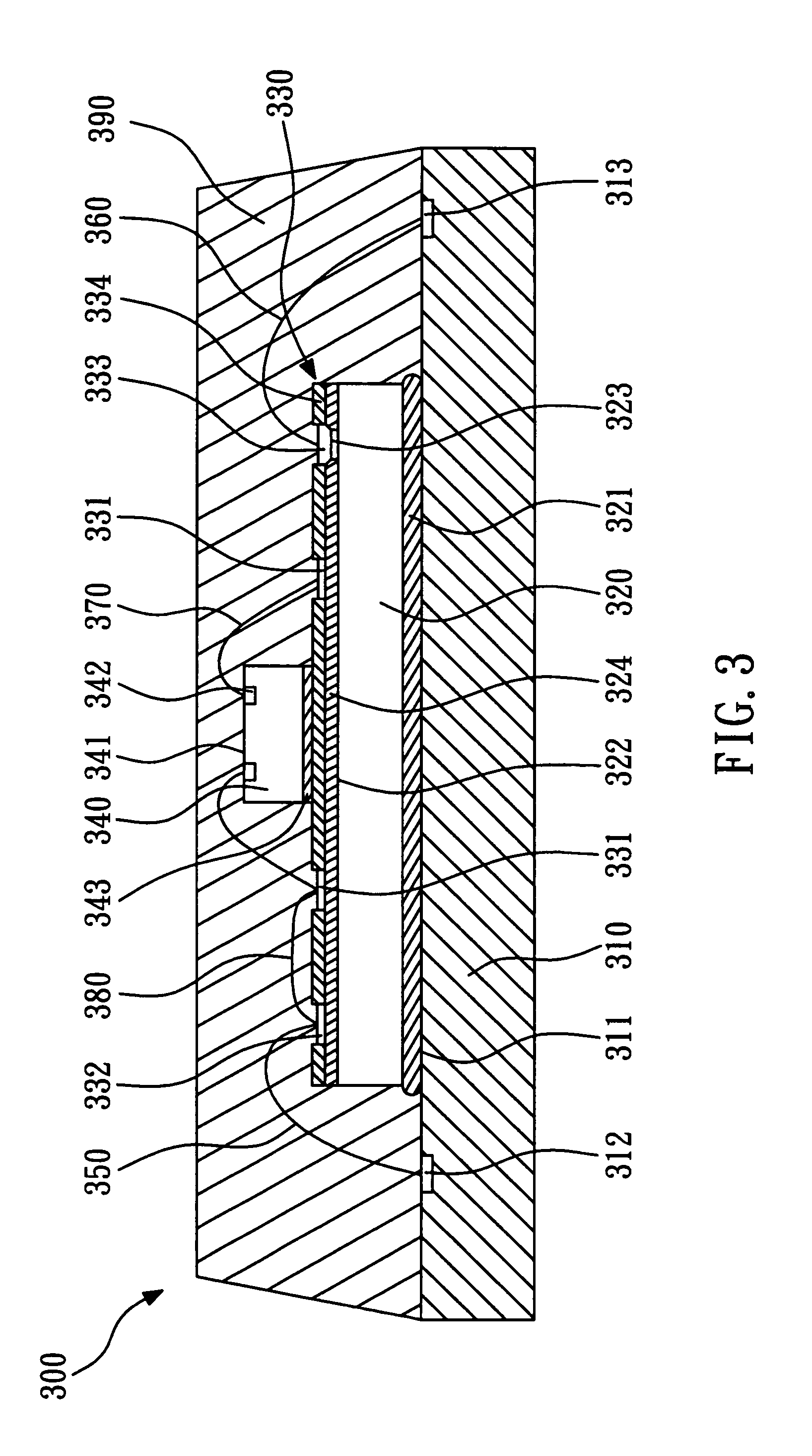
[0015]Referring to FIG. 3, according to the present invention, a multi-chip stack package 300 mainly comprises a substrate 310, a first chip 320, a redistribution structure 330, a second chip 340, and a plurality of first bonding wires 350. The substrate 310 comprises an upper surface 311 and a plurality of connecting pads 312, 313 formed on the upper surface 311. The substrate 310 can be a printed circuit board. The first chip 320 comprises a first active surface 322 and a plurality of bonding pads 323 formed on the first active surface 322, and it is stacked on the upper surface 311 of the substrate 310 through an adhesive 321, by the first active surface 322 facing upwards. In this embodiment, the first bonding pads 323 are arranged at the periphery of the first active surface 322. A passivation layer 324 is formed on the first active surface 322, and exposes the first bonding pads 323. The first chip 320 can be a memory chip.

[0016]The redistribution structure 330 comprises a plu...

second embodiment

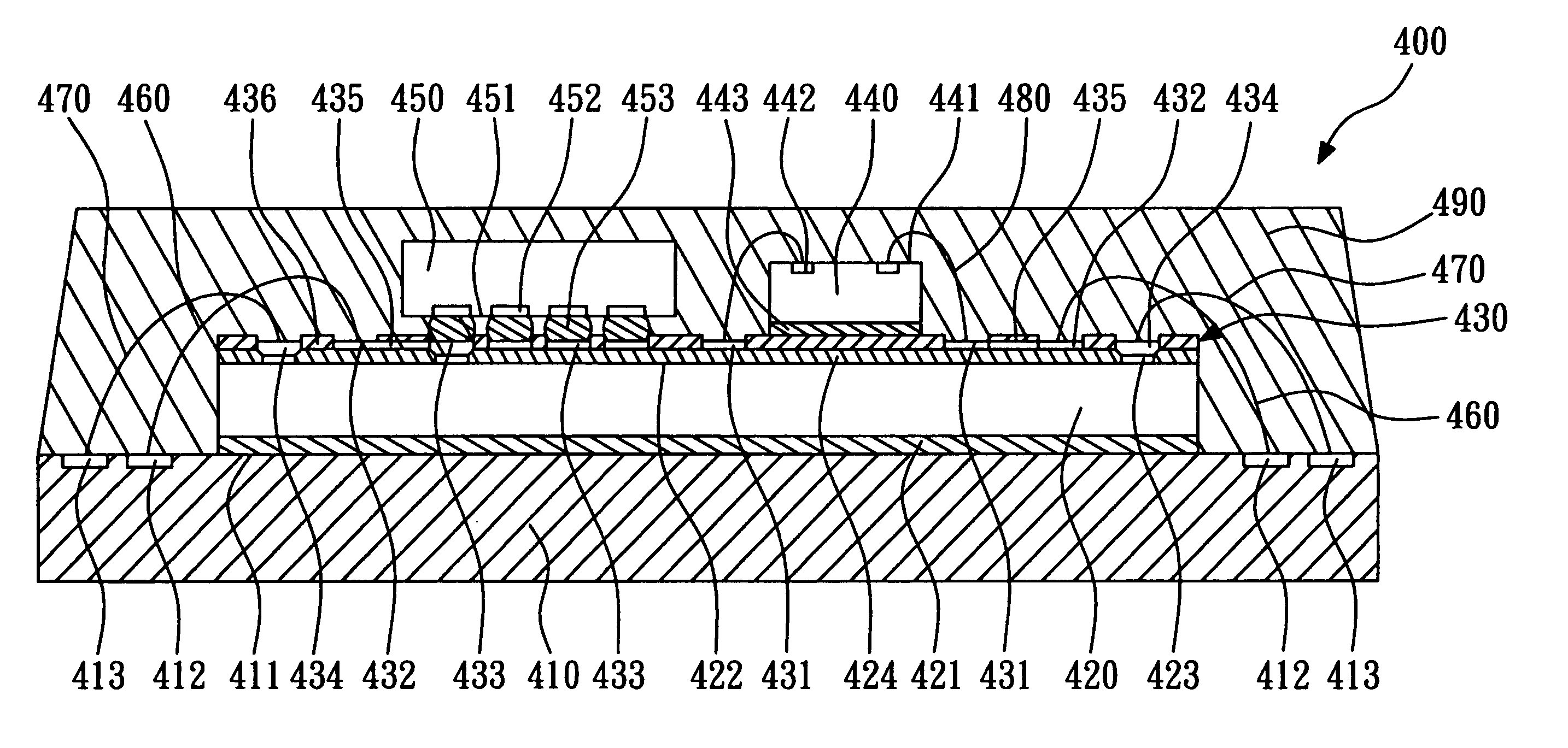
[0020]Referring to FIG. 4, according to the present invention, a multi-chip stack package 400 mainly comprises a substrate 410, a first chip 420, a redistribution structure 430, a second chip 440, a third chip 450, and a plurality of first bonding wires 460. The substrate 410 comprises an upper surface 411 and a plurality of connecting pads 412, 413 formed on the upper surface 411.

[0021]The first chip 420 comprises a first active surface 422 and a plurality of first bonding pads 423 formed on the first active surface 422. The first chip 420 is attached to the upper surface 411 of the substrate 410 through an adhesive 421, by the first active surface 422 facing upwards. A passivation layer 424 is formed on the first active surface 422 and exposes the first bonding pads 423.

[0022]The redistribution structure 430 formed on the first active surface 422 of the first chip 420 comprises a plurality of first intermediate pads 431, a plurality of second intermediate pads 432, a plurality of ...


PUM


Abstract

A multi-chip stack package mainly includes a substrate, a first chip, a redistribution structure and at least one second chip. The first chip is disposed on the substrate with an active surface facing upwards. The redistribution structure includes a plurality of first intermediate pads, a plurality of second intermediate pads and a plurality of external pads. The first intermediate pads, the second intermediate pads, and the external pads are formed on the first active surface of the first chip, wherein the first intermediate pads and the second intermediate pads are electrically connected with each other. The second chip is disposed on the redistribution structure, and electrically connected to the first intermediate pads. The second intermediate pads are electrically connected to the substrate through a plurality of bonding wires, so that the second chip and the substrate are electrically conducted, and the connection length of the bonding wires is reduced.

Description

BACKGROUND OF THE INVENTION[0001]1. Field of the Invention[0002]The present invention relates to a multi-chip stack package, and more particularly to a multi-chip stack package that can reduce the length of bonding wires.[0003]2. Description of the Related Art[0004]To achieve the small size of the multi-chip package structure, a plurality of chips are stacked on a substrate, and electrically connected to the substrate by wire bonding or flip-chip bonding. Referring to FIG. 1, a conventional multi-chip stack package 100 formed by wire bonding comprises a substrate 110, a first chip 120, a second chip 130, and a plurality of bonding wires 140, 150. The first chip 120 is disposed on the substrate 110, and electrically connected to the substrate 110 through the bonding wires 140. The second chip 130 is stacked on the first chip 120, with a dimension smaller than that of the first chip 120, and electrically connected to the substrate 110 through the bonding wires 150. Since the second ch...

Claims


Application Information

Patent Timeline
Patent Type & Authority Patents(United States)
IPC IPC(8): H01L23/48H01L23/52H01L29/40H01L23/31H01L25/065
CPCH01L25/0652H01L25/0657H01L23/3121H01L2224/16145H01L2224/32145H01L2224/48145H01L2224/73265H01L2225/06506H01L2225/0651H01L2225/06513H01L2225/06527H01L2224/0554H01L2224/05567H01L2224/05573H01L2224/4813H01L2924/00014H01L2924/181H01L2924/00012H01L2224/05599H01L2224/0555H01L2224/0556
Inventor KANG, JUNG-KUNLIN, CHIN-HSIEN
Owner ADVANCED SEMICON ENG INC
Why Eureka
Try Eureka