Image-sensing apparatus for compensating video signal of a plurality of channels

Active Publication Date: 2007-05-15
JVC KENWOOD CORP A CORP OF JAPAN
View PDF19 Cites 21 Cited by
  • Summary
  • Abstract
  • Description
  • Claims
  • Application Information

AI Technical Summary

Benefits of technology

[0009]Other object of present invention is to provide an image-sensing apparatus which eliminates an influence of smear in the output signal.
[0010]Other object of present invention is to provide an image-sensing apparatus which suppresses an influence of shading occurred in the image sensing device.
[0011]Other object of present invention is to provide an image-sensin

Problems solved by technology

In case that a clock signal has higher frequency, various signal processing circuits in a subsequent stage need t

Method used


Image

  • Image-sensing apparatus for compensating video signal of a plurality of channels
  • Image-sensing apparatus for compensating video signal of a plurality of channels
  • Image-sensing apparatus for compensating video signal of a plurality of channels

Examples


Example

[0062]FIG. 5 is a block diagram of an image-sensing apparatus according to a first embodiment of the present invention.

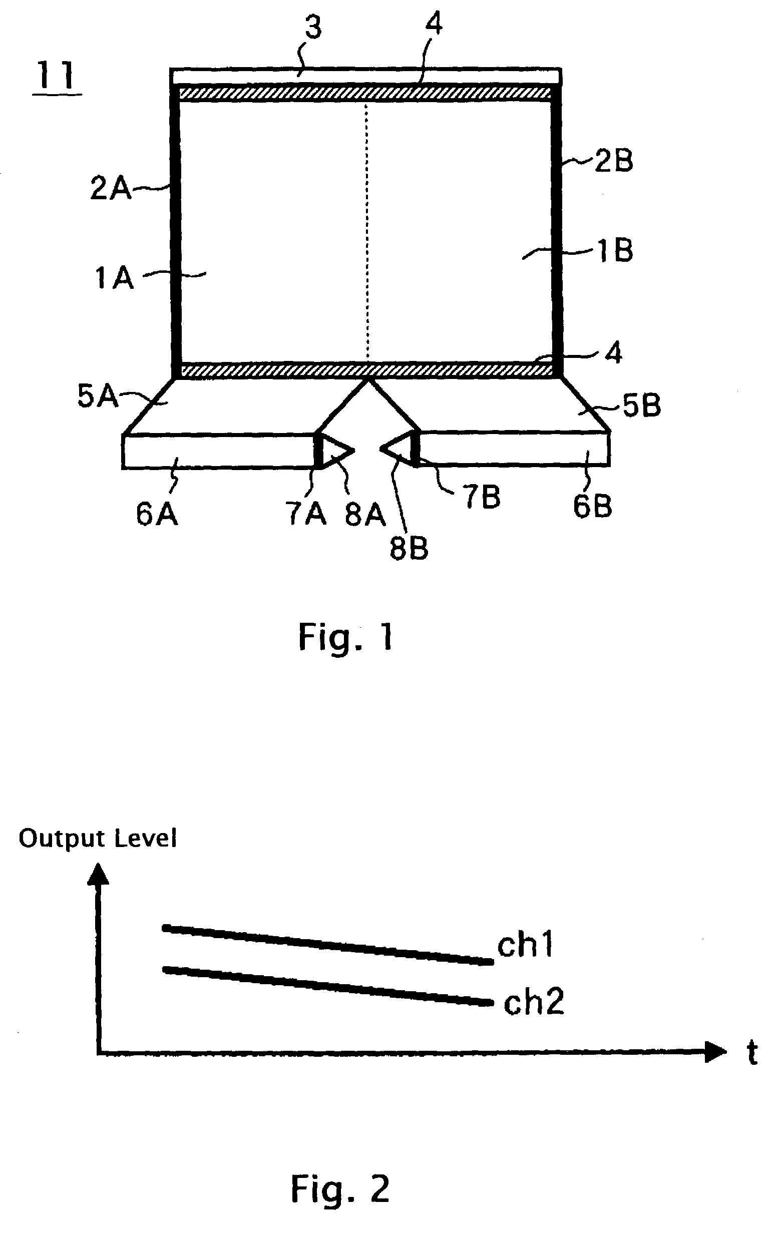
[0063]In FIG. 5, the image-sensing apparatus is composed of an image-sensing device 11, a CDS circuit 12, an ADC circuit 13, a timing generator 14, a control circuit 15, a detection circuit 16, a gain compensation 17, and a YC processor 18.

[0064]The image-sensing device 11 has the same construction of the image-sensing device shown in FIG. 1. The vertical pilot adder 3 directly adds a pilot signal having predetermined level to the video signal generated from each of the divided areas 1A and 1B. The way of adding electric charge to the video signal is not limited but include the way described in, for example Japanese Patent Application Laid-open Publication Nos. 6(1994)-86181 and 8(1996)-125934.

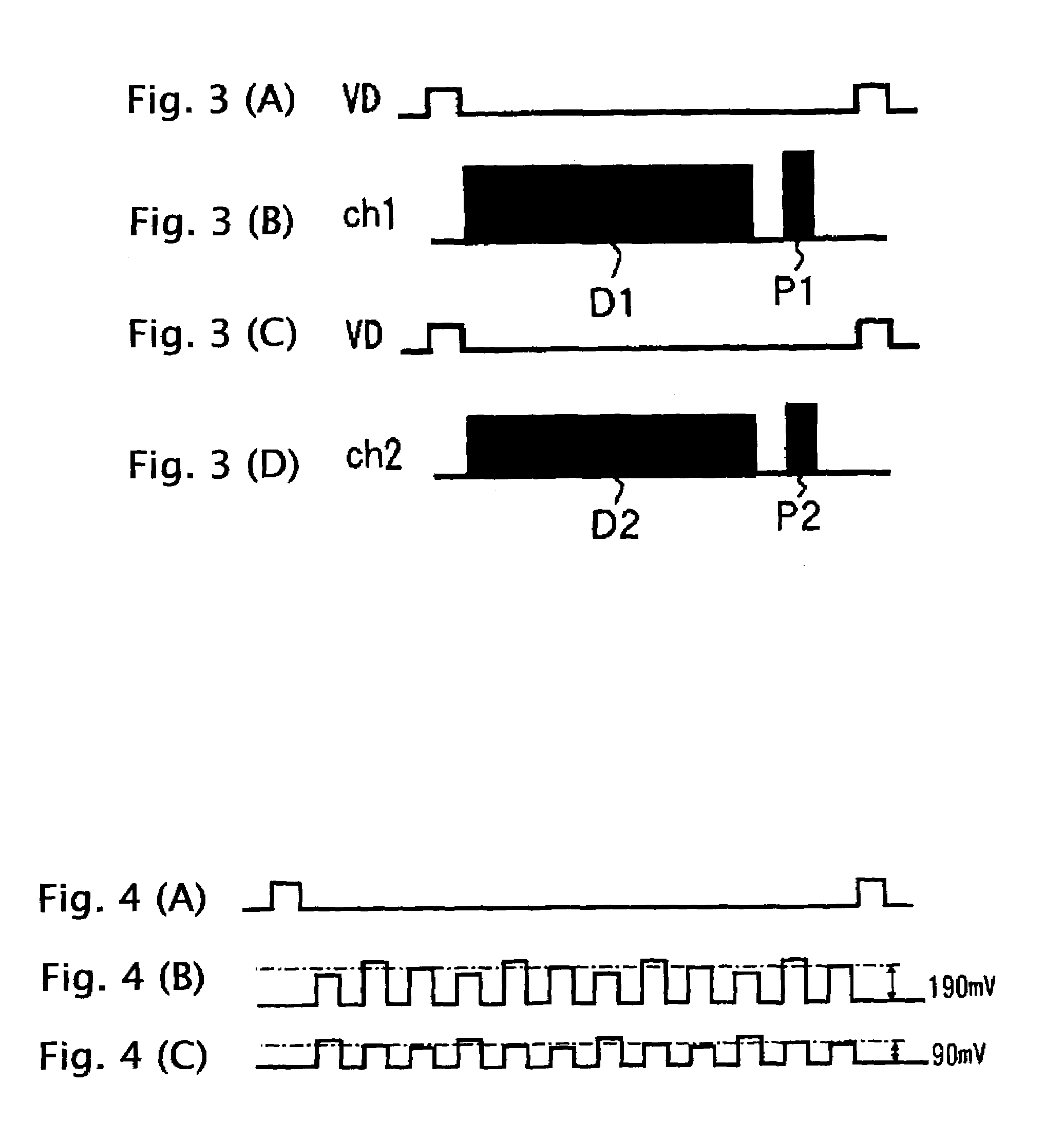
[0065]The way of adding electric charge is conducted by supplying a pulse to predetermined electric pole. An irregular change of pilot signal level is caused by a potential ba...

Example

[0082]FIG. 8 is a block diagram of an image-sensing apparatus according to a second embodiment of the present invention.

[0083]In FIG. 8, the image-sensing apparatus is composed of the image-sensing device 11, the CDS circuit 12, the timing generator 14 and the YC processor 18, and a gain compensation 22, an AD converter 23, a detection circuit 24, and a control circuit 21. The image-sensing apparatus according to the second embodiment of the present invention is characterized in that the gain compensation 22 conducts a gain compensating operation.

[0084]The image-sensing device 11 outputs two channel output signals to the CDS circuit 12. The CDS circuit 12 conducts OB clamp processing and correlation-double-sampling (CDS) processing on each channel signal. Then the CDS circuit 12 provides output signals to the gain compensation 22.

[0085]The gain compensation 22 conducts level compensation on the output signals supplied from the CDS circuit 12 by a control signal provided from the con...

Example

[0109]FIG. 13 is a block diagram of an image-sensing apparatus according to a third embodiment of the present invention.

[0110]In FIG. 13, an image-sensing apparatus is composed of an image-sensing device 71, a timing generator 72, a CDS circuit 73, a control circuit 74, an AD converter 75, a detection circuit 76, a shading compensation circuit 77, a channel signal processor 78 and a YC processor 79.

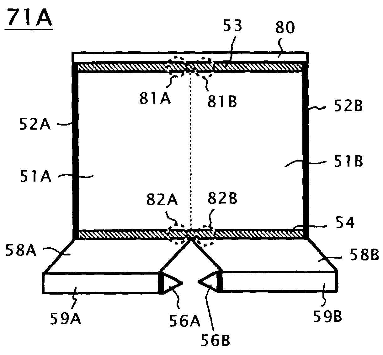
[0111]FIG. 14 is a plan view of the image-sensing device 71A. Most elements of the image-sensing device 71A are the same as the image-sensing device 11B, except that the image-sensing device 71A has a pilot signal adder 80 on the top of the OB area 53.

[0112]In the case of the image-sensing device 71A which has almost the same construction of the image-sensing device 11B, the output of OB signal is affected by a transferring efficiency of the HCCDS 59A, 59B and vertical CCDS not shown.

[0113]On the other hand, the image-sensing apparatus utilizes an OB signal as a reference signal for condu...


PUM


Abstract

An image-sensing apparatus for compensating video signal of a plurality of channels, adds an electric charge of a pilot signal on a signal vertically transferred in an image-sensing device 11. A pixel area of the image-sensing device 11 is divided into a plurality of pixel areas to obtain an output signal of a plurality of channels. The pilot signal is add to an output signal of each pixel area corresponding to each channel for twice a field period, and for different electric potential. The control circuit 15 obtains a difference between the two pilot signals in one filed period, and controls the gain compensation 17 to make the pilot signal level in each channel equal. Additionally, the pilot signal is not used for compensation but the previous signal is used when a smear element is detected from the output signal of each channel.

Description

BACKGROUND OF THE INVENTION[0001]1. Field of the Invention[0002]The present invention relates to an image-sensing apparatus for compensating video signal of a plurality of channels, and especially relates to an image-sensing device for generating a plurality of channel outputs and for compensating an output signal level in each channel.[0003]2. Description of the Related Art[0004]Recently, a micro-fabrication technology has been developed remarkably for manufacturing large scale semiconductor integrated circuit (LSI). In addition, there is a need in the market for image-sensing apparatus which provides high resolution pictures. The image-sensing apparatus includes an image-sensing device which converts an optical image into a video signal, and various signal processors to conduct signal conditioning on the video signal outputted from the image-sensing device.[0005]In order to obtain high resolution pictures, a number of pixels in the image-sensing device becomes bigger because more ...

Claims


Application Information

Patent Timeline
IPC IPC(8): H04N5/335H04N9/64H04N5/217H04N5/359H04N5/372
CPCH04N5/3595H04N5/361H04N5/37213H04N25/625H04N25/63H04N25/713
Inventor MIYAHARA, HIROYUKIKUNIMI, HIROYASUNISHIYAMA, HIROSHIOURA, TETSUYAIBARAKI, TAKESHI
Owner JVC KENWOOD CORP A CORP OF JAPAN
Why Eureka
Try Eureka