
System for switching data using dynamic scheduling

a dynamic scheduling and data technology, applied in the field of data switching, can solve the problems of data traffic based on static models, data transfer blockage, data traffic influence, etc., and achieve the effect of reducing latency and greater performan

Active Publication Date: 2007-05-15
UNWIRED BROADBAND INC
View PDF17 Cites 105 Cited by
  • Summary
  • Abstract
  • Description
  • Claims
  • Application Information

AI Technical Summary

Benefits of technology

[0012]The present architecture may provide a number of advantages over conventional architectures. Primarily, since the scheduling of data transfers can be dynamically adapted to the changing character of the incoming data traffic, the system may experience lower latency and greater performance then conventional systems. Since an active schedule is maintained until a new schedule can be computed and implemented, little or no additional latency results from implementation of the new schedule. The computation of the new schedule may be based on various types of algorithms, such as statistical, optimization or heuristic algorithms, or even a combination of these different types of algorithms.

Problems solved by technology

One of the problems that may be encountered in data switching is the blocking of data transfers because the data transfer path is already in use.
This may significantly impact the latency of the data transfers.
One of the disadvantages of these conventional systems is that they are based on static models of the data traffic.
If the actual traffic varies from the anticipated scenario, the systems cannot adapt to the new behavior.
While the statistical model upon which the scheduling of the data is based may be ideal for certain cases, it will likely be far from ideal in other cases.
The performance of the systems may suffer as a result.

Method used


Image

  • System for switching data using dynamic scheduling
  • System for switching data using dynamic scheduling
  • System for switching data using dynamic scheduling

Examples


Embodiment Construction

[0036]A preferred embodiment of the invention is described below. It should be noted that this and any other embodiments described below are exemplary and are intended to be illustrative of the invention rather than limiting.

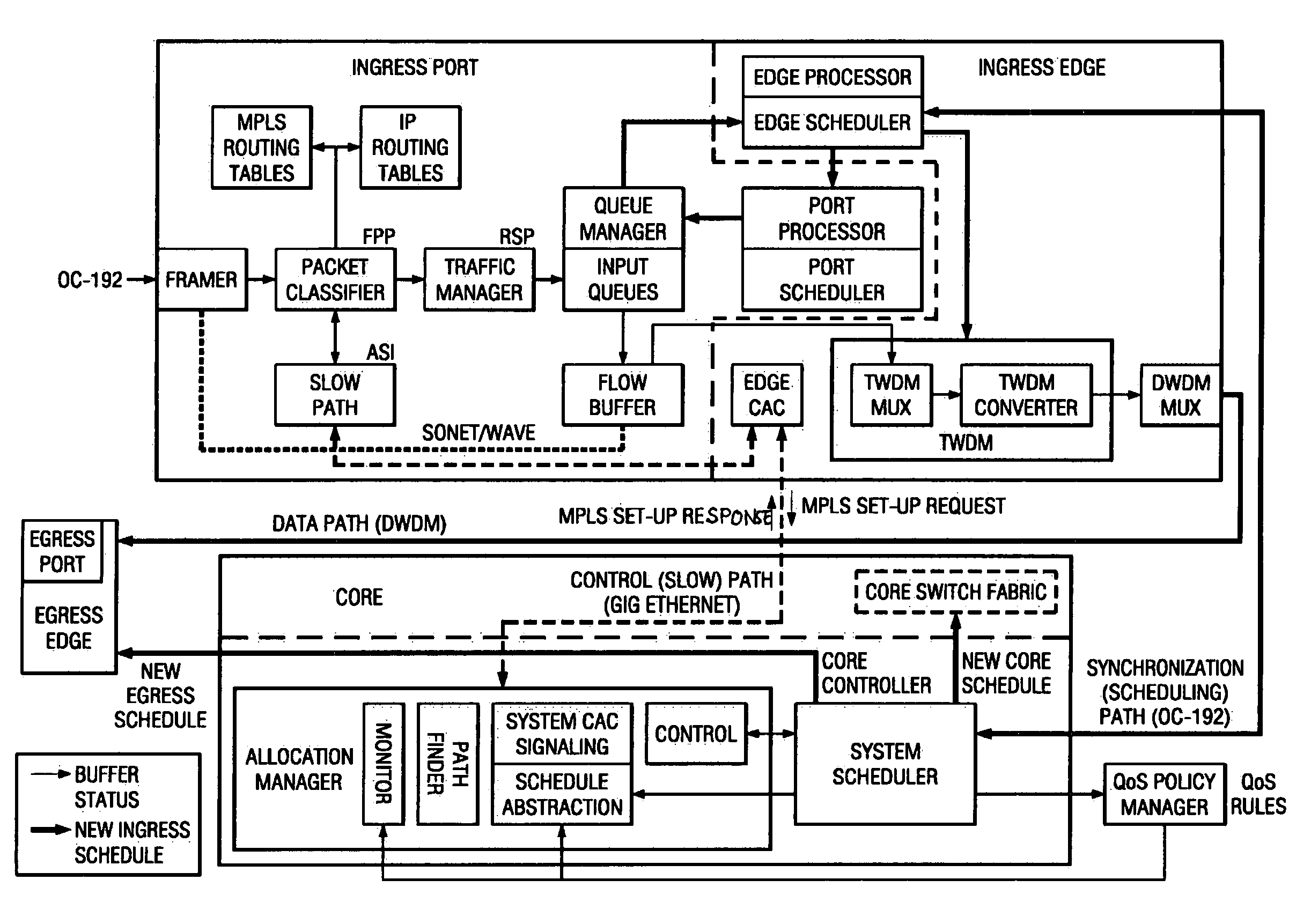
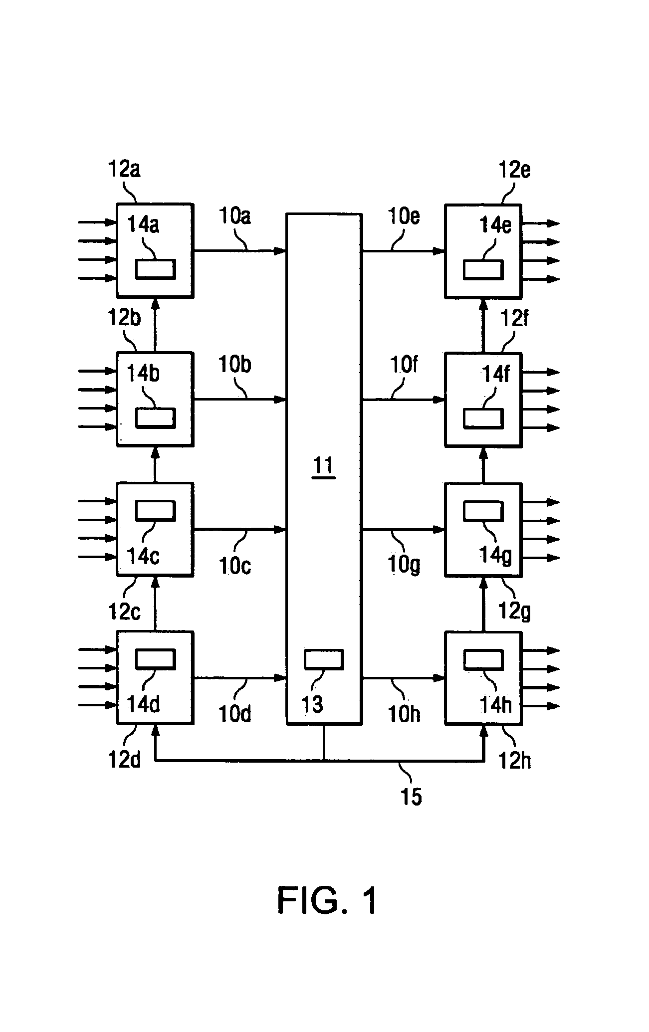
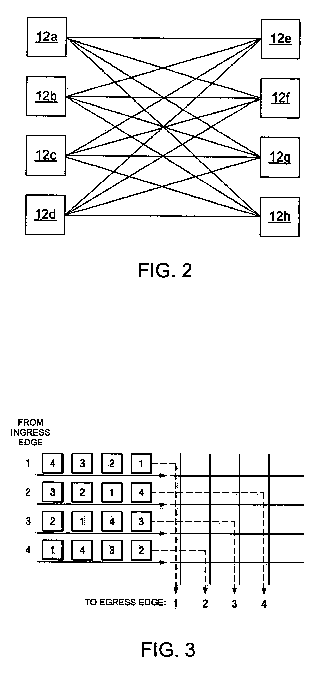
[0037]Broadly speaking, the invention comprises an architecture for a data switching system, wherein dynamic scheduling is used to maintain the sufficiency of the system's data transfer performance despite changes in the character of the incoming data traffic. In one embodiment, the present architecture comprises an optical switching core coupled to a plurality of edge units. The edge units each include a set of ingress ports and a set of egress ports. The switching core has a scheduler that maintains two non-blocking data transfer schedules, only one of which is active at any given time. Data is transferred from the ingress ports to the egress ports according to the active schedule. The switching core scheduler monitors data received from the edge units which i...


PUM


Abstract

An architecture and related systems for improving the performance of non-blocking data switching systems. In one embodiment, a switching system includes an optical switching core coupled to a plurality of edge units, each of which has a set of ingress ports and a set of egress ports. The switching system also contains a scheduler that maintains two non-blocking data transfer schedules, only one of which is active at a time. Data is transferred through the switching system according to the active schedule. The scheduler monitors the sufficiency of data transferred according to the active schedule and, if the currently active schedule is insufficient, the scheduler recomputes the alternate schedule based on demand data received from the edges / ports and activates the alternate schedule. A timing mechanism is employed to ensure that the changeover to the alternate schedule is essentially simultaneous among the components of the system.

Description

RELATED APPLICATIONS[0001]The present application claims priority to U.S. Provisional Patent Application Ser. No. 60 / 306,954 entitled “System and Method for Dynamic Scheduling Implementation to Eliminate Blocking and Optimizing Performance on an All-Optical Switch” filed on Jul. 20, 2001, which is incorporated by reference as if set forth herein in its entirety.BACKGROUND[0002]1. Field of the Invention[0003]The invention relates generally to the switching of data and more particularly to the transfer of data through a switching core in a non-blocking manner, wherein non-blocking schedules are dynamically computed and implemented to maintain the sufficiency of data transfers through the switching core.[0004]2. Related Art[0005]One of the problems that may be encountered in data switching is the blocking of data transfers because the data transfer path is already in use. In other words, while a first port is transferring data to a second port, the second port cannot receive data from ...

Claims


Application Information

Patent Timeline
Patent Type & Authority Patents(United States)
IPC IPC(8): H04L12/28
CPCH04L49/254H04L49/205
Inventor BEST, ROBERT E.CHANDRASEKARAN, RAMASWAMYRUDIN, III, JOHN R.HU, ROSE Q.WATSON, JEFF L.TAMIL, LAKSHMAN S.FABBRI, ALESSANDRO
Owner UNWIRED BROADBAND INC
Learn More