Optical fiber cables

a technology of optical fiber cables and fiber optic cables, applied in the field of optical fiber cables, can solve the problems of cable fiber retraction, time-consuming installation and repair of gel filled cables, cosmetic or other problems, etc., and achieve the effect of compact size and low cos

Active Publication Date: 2007-05-15
FURAKAWA ELECTRIC NORTH AMERICA INC
View PDF6 Cites 63 Cited by
  • Summary
  • Abstract
  • Description
  • Claims
  • Application Information

AI Technical Summary

Benefits of technology

[0009]We have designed an optical fiber cable suitable for drop cable applications that has a compact flat profile. The new design has a binary construction of two subunits molded together side-by-side. Preferably, the two subunits match geometrically. One subunit contains the optical fibers, and the other unit contains a strength member. The subunit containing the optical fibers also contains one or more separate and additional strength members. In a preferred embodiment, the cable has a coupled fiber design, and is dry. The coupled design forms a unitary assembly that is robust, and resistant to fiber retraction. The combination of a flat cable profile, with a strength member that is easily separated from the optical fiber subunit, and with a separate strength member in the optical fiber subunit, results in a design that is well adapted to multiple drop cable applications.

Problems solved by technology

However, gel filled cables are time consuming to install and repair, as the gel must be completely removed from the optical fiber prior to splicing operations.
Moreover, since the drop wire is typically attached to the side of a customer's home or building, bleeding of ingredients in the cable onto the customer's building may cause cosmetic or other problems.
Since aerial drop cables are subjected to considerable movement and sag due to wind and ice build-up, and due to mechanical strain caused by differential thermal expansion, aerial drop cables commonly have a loose fiber design.
However, a drawback to this design is that the cable may suffer fiber retraction due to the movement just mentioned.
Excessive fiber retraction may result in damage or breakage of the fibers.

Method used


Image

  • Optical fiber cables
  • Optical fiber cables
  • Optical fiber cables

Examples


Embodiment Construction

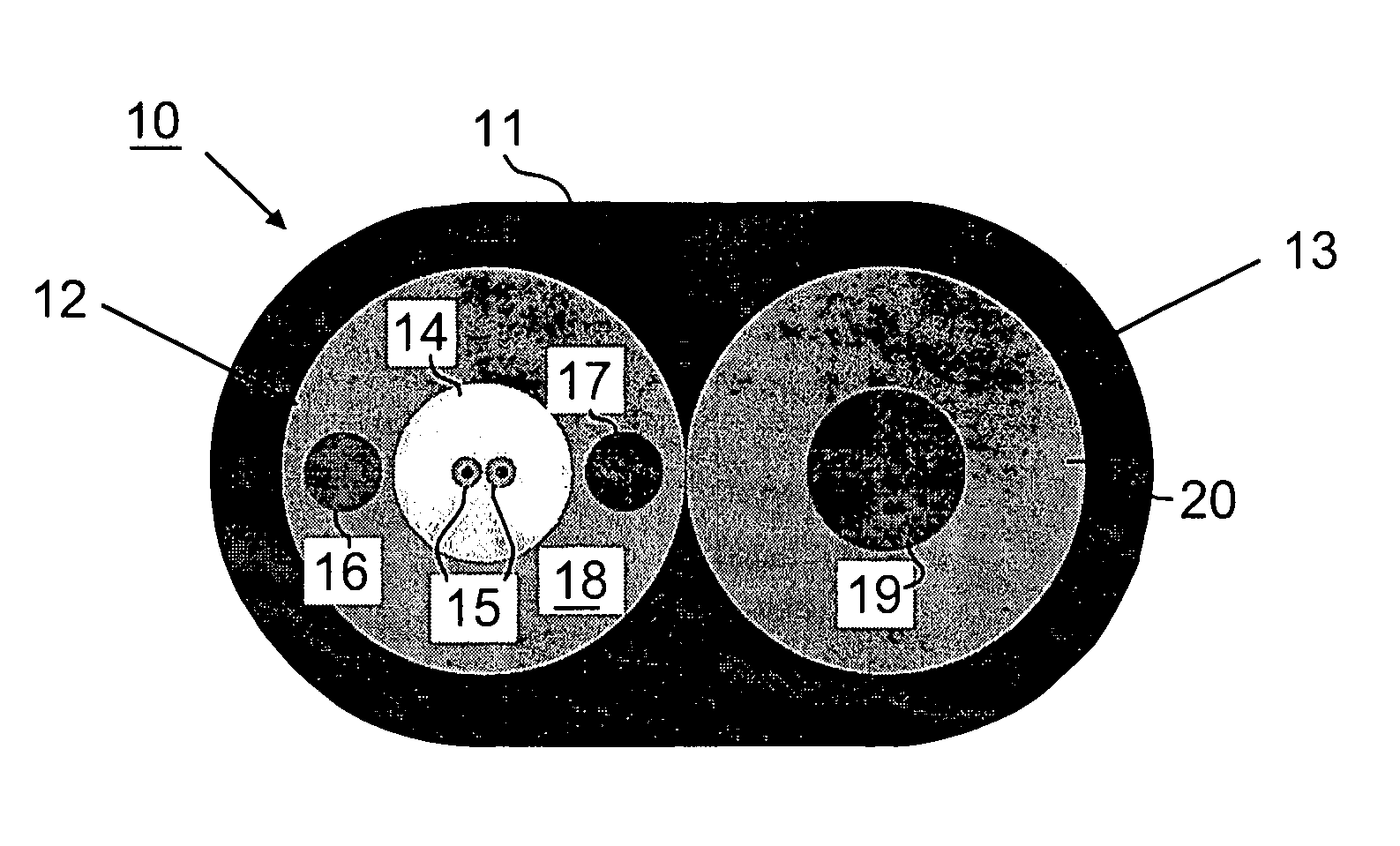
[0016]Referring to FIG. 1, a flat optical fiber drop cable is shown generally at 10, with optical fiber subunit 12 and strength member subunit 13. Both are encased in encasement 11. The subunits are preferably approximately the same size, as shown, which imparts symmetry to the cable cross section. Alternatively, they may be different sizes. Symmetry, if desired, may be realized in the latter case by using a symmetrical die for extruding the encasement 11. In the embodiment shown, the optical fiber subunit contains two fibers 15. One fiber, or more than two fibers, may also be used.

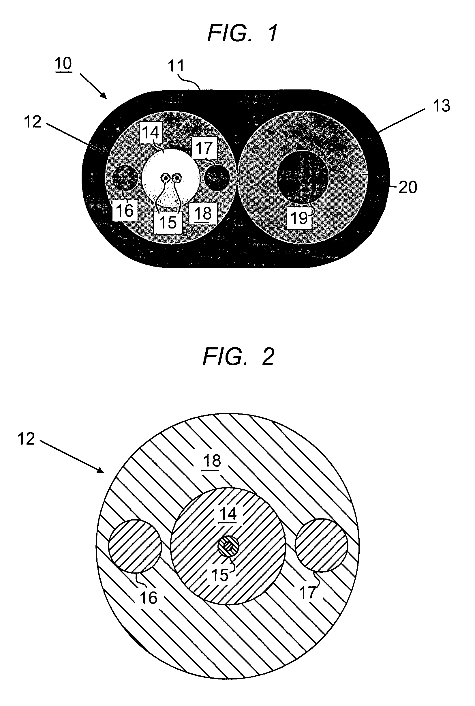
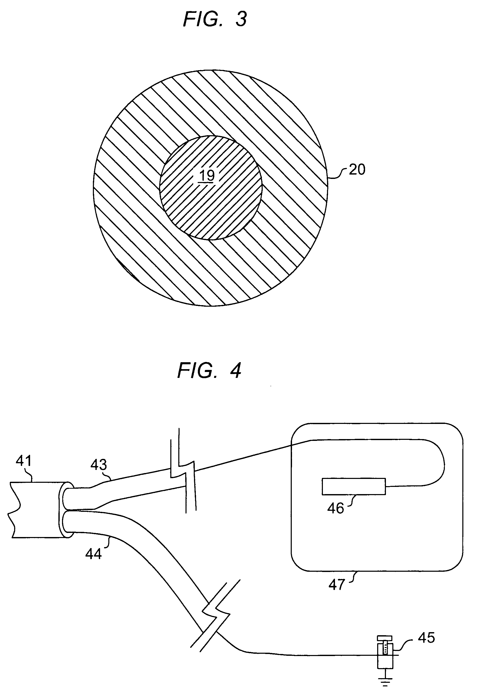
[0017]The subunits 12 and 13 are shown in more detail in FIGS. 2 and 3. FIG. 2 is a cross section of the optical fiber subunit 12. Here, there is one optical fiber shown at 15. The optical fiber is a conventional coated glass or plastic fiber. The optical fiber subunit may have a loose fiber design, where the optical fiber floats in a tube. However, the preferred design is that illustrated, where the opti...


PUM


Abstract

The specification describes an optical fiber drop cable with a flat configuration and having two side-by-side subunits. One of the subunits contains a cable strength member, e.g. a steel wire or stranded wire. The other subunit is an optical fiber subunit, which contains the optical fiber(s), and also contains one or more additional strength members. In a preferred embodiment, the cable is dry, and has conformal encasements that couple the optical fiber(s) to the outer cable sheath.

Description

FIELD OF THE INVENTION[0001]This invention relates to optical fiber cables specially adapted for drop line applications.BACKGROUND OF THE INVENTION[0002]Fiber-to-the-premises (FTTP) from local telephone and cable service providers is rapidly being implemented. This service requires a broadband optical fiber distribution network comprising local optical fiber distribution cables that are installed in neighborhood and city streets. The local distribution cable is a large fiber count (multi-fiber) cable. Single fiber or few fiber cables are used for the “drop” line from the street to the premises. In many cases, aerial drop lines are used, and these have special requirements. In other cases, buried drop lines are used, and these have different specific requirements.[0003]Optical fiber drop cables are made in several designs. Most of these designs mimic earlier copper cable versions. Physical resemblance is deliberate, so that the external cable appearance matches that of existing coppe...

Claims


Application Information

Patent Timeline
Patent Type & Authority Patents(United States)
IPC IPC(8): G02B6/44
CPCG02B6/4422G02B6/4429G02B6/4463G02B6/50
Inventor BOCANEGRA, LUIS M.DEBBAN, HAROLD P.WEIMANN, PETER A.
Owner FURAKAWA ELECTRIC NORTH AMERICA INC
Why Eureka
Try Eureka