Feedback loop for spam prevention

Inactive Publication Date: 2007-05-15
MICROSOFT TECH LICENSING LLC
View PDF83 Cites 199 Cited by
  • Summary
  • Abstract
  • Description
  • Claims
  • Application Information

AI Technical Summary

Benefits of technology

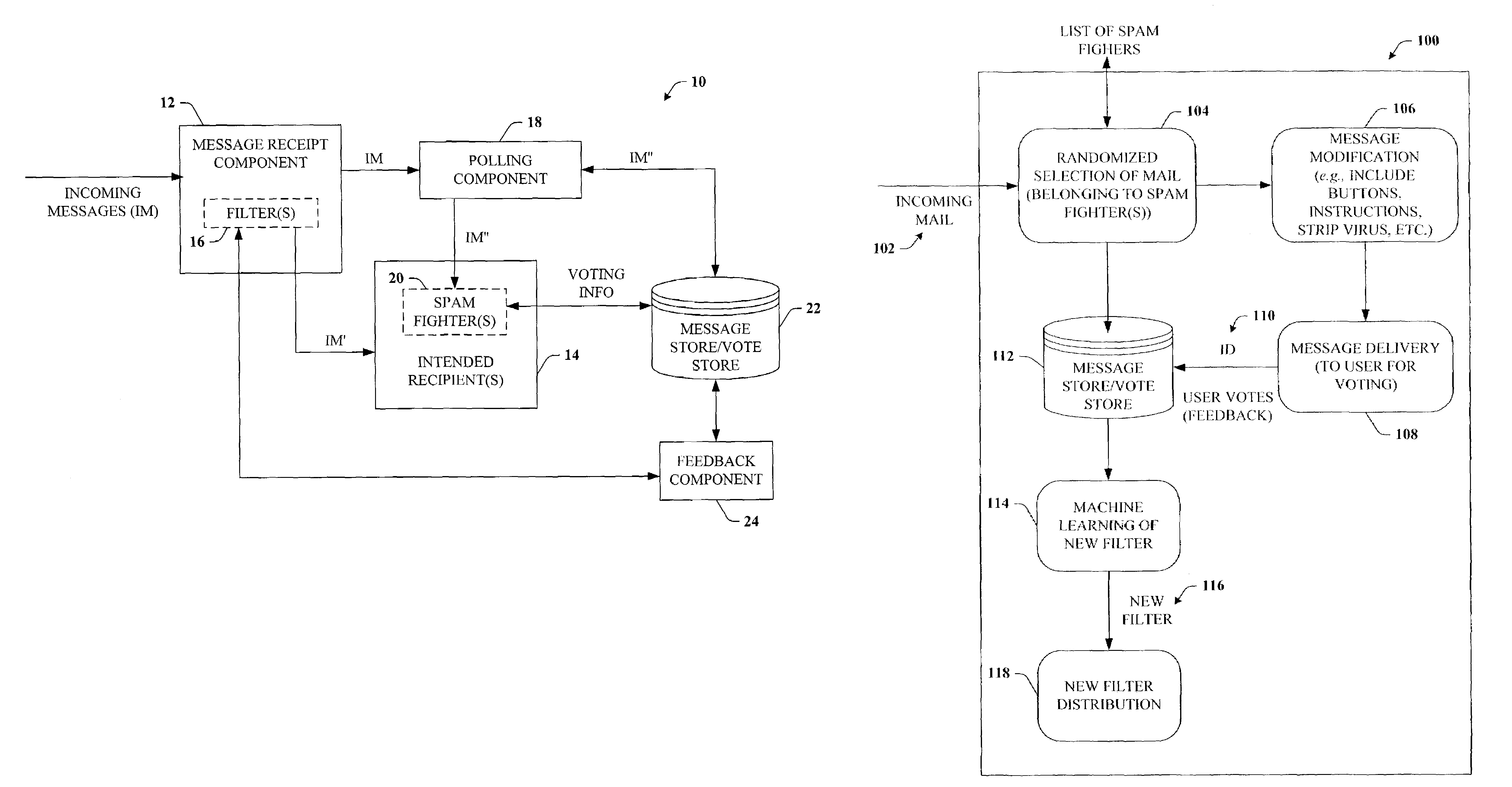
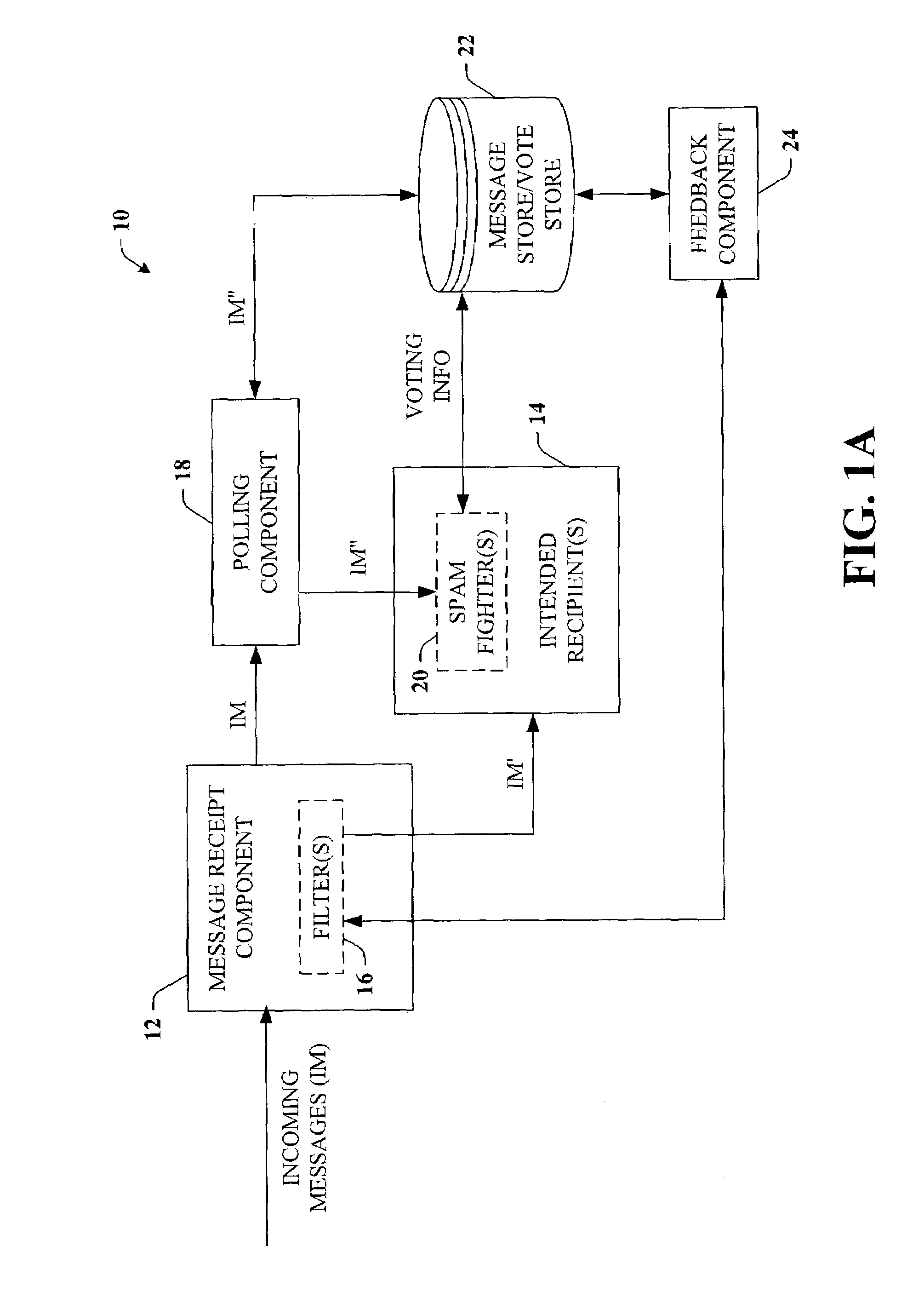
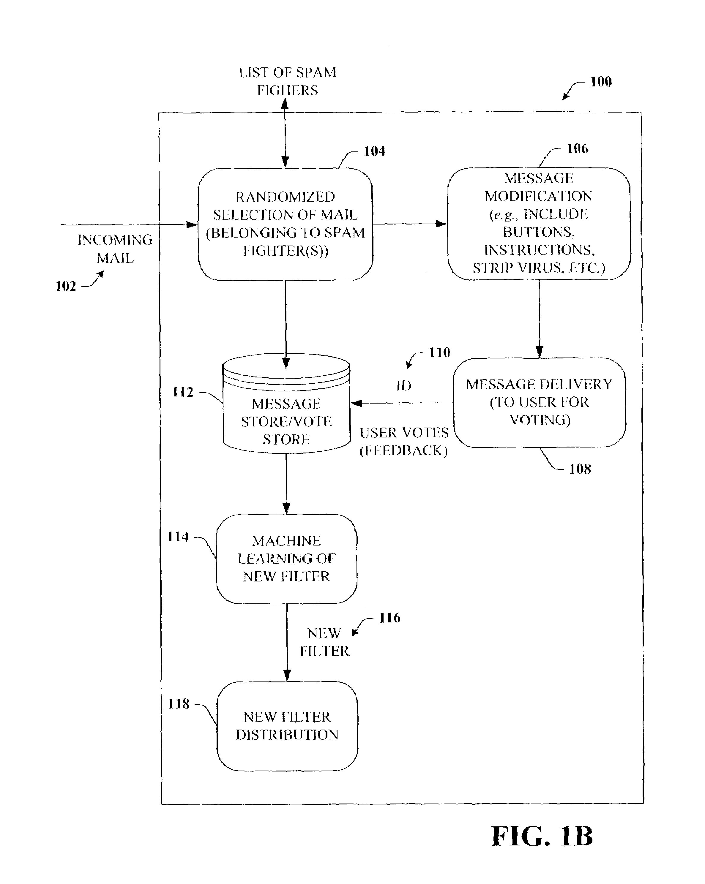
[0011]Unlike conventional spam filters, more accurate spam filters can be created by training spam filters in accordance with the feedback technique of the subject invention so as to learn to distinguish between good mail and spam, thereby mitigating biased and inaccurate filtering. The feedback is accomplished at least in part by polling any suitable number of users to obtain feedback on their incoming email. Users, identified as spam-fighters, are tasked with voting on whether a selection of incoming messages is either legitimate mail or junk mail. Both positive and negative classifications of incoming email are desired to mitigate improperly filtering out as spam mail that is good (e.g., not spam) intended for a user. The respective classifications along with any other information associated with each mail transaction are moved to a database to facilitate training the spam filters. The database and related components can compile and store properties for selected message(s) (or selected mail transaction), which includes user properties, user voting information and histories, message properties such

Problems solved by technology

Individuals and entities (e.g., businesses, government agencies) are becoming increasingly inconvenienced and oftentimes offended by junk messages.
As such, junk e-mail is now or soon will become a major threat to trustworthy computing.
Furthermore, not all users agree on what is and is not, junk/spam.
Unfortunately, such manually intensive training techniques are undesirable to many users due to the complexity associated with such training let alone the amount of time required to properly effect such training.
In addition, such manual training techniques are

Method used


Image

  • Feedback loop for spam prevention
  • Feedback loop for spam prevention
  • Feedback loop for spam prevention

Examples


Example

[0028]The present invention is now described with reference to the drawings, wherein like reference numerals are used to refer to like elements throughout. In the following description, for purposes of explanation, numerous specific details are set forth in order to provide a thorough understanding of the present invention. It may be evident, however, that the present invention may be practiced without these specific details. In other instances, well-known structures and devices are shown in block diagram form in order to facilitate describing the present invention.

[0029]As used in this application, the terms “component” and “system” are intended to refer to a computer-related entity, either hardware, a combination of hardware and software, software, or software in execution. For example, a component may be, but is not limited to being, a process running on a processor, a processor, an object, an executable, a thread of execution, a program, and / or a computer. By way of illustration...


PUM


Abstract

The subject invention provides for a feedback loop system and method that facilitate classifying items in connection with spam prevention in server and/or client-based architectures. The invention makes uses of a machine-learning approach as applied to spam filters, and in particular, randomly samples incoming email messages so that examples of both legitimate and junk/spam mail are obtained to generate sets of training data. Users which are identified as spam-fighters are asked to vote on whether a selection of their incoming email messages is individually either legitimate mail or junk mail. A database stores the properties for each mail and voting transaction such as user information, message properties and content summary, and polling results for each message to generate training data for machine learning systems. The machine learning systems facilitate creating improved spam filter(s) that are trained to recognize both legitimate mail and spam mail and to distinguish between them.

Description

TECHNICAL FIELD[0001]This invention is related to systems and methods for identifying both legitimate (e.g., good mail) and undesired information (e.g., junk mail), and more particularly to classifying electronic mail correspondence for spam prevention.BACKGROUND OF THE INVENTION[0002]The advent of global communications networks such as the Internet has presented commercial opportunities for reaching vast numbers of potential customers. Electronic messaging, and particularly electronic mail (“email”), is becoming increasingly pervasive as a means for disseminating unwanted advertisements and promotions (also denoted as “spam”) to network users.[0003]The Radicati Group, Inc., a consulting and market research firm, estimates that as of August 2002, two billion junk e-mail messages are sent each day—this number is expected to triple every two years. Individuals and entities (e.g., businesses, government agencies) are becoming increasingly inconvenienced and oftentimes offended by junk ...

Claims


Application Information

Patent Timeline
IPC IPC(8): G06F15/173G06FG06F1/00G06F17/30G06Q10/10H04L9/00H04L9/32H04L12/54H04L12/58H04L29/02
CPCG06Q10/107H04L51/12H04L12/585H04L51/212G06Q50/30
Inventor ROUNTHWAITE, ROBERT L.GOODMAN, JOSHUA T.HECKERMAN, DAVID E.MEHR, JOHN D.HOWELL, NATHAN D.RUPERSBURG, MICAH C.SLAWSON, DEAN A.
Owner MICROSOFT TECH LICENSING LLC
Why Eureka
Try Eureka