
High-speed module, device and method for decoding a concatenated code

Inactive Publication Date: 2007-05-15
FRANCE TELECOM SA +1
View PDF21 Cites 16 Cited by
  • Summary
  • Abstract
  • Description
  • Claims
  • Application Information

AI Technical Summary

Benefits of technology

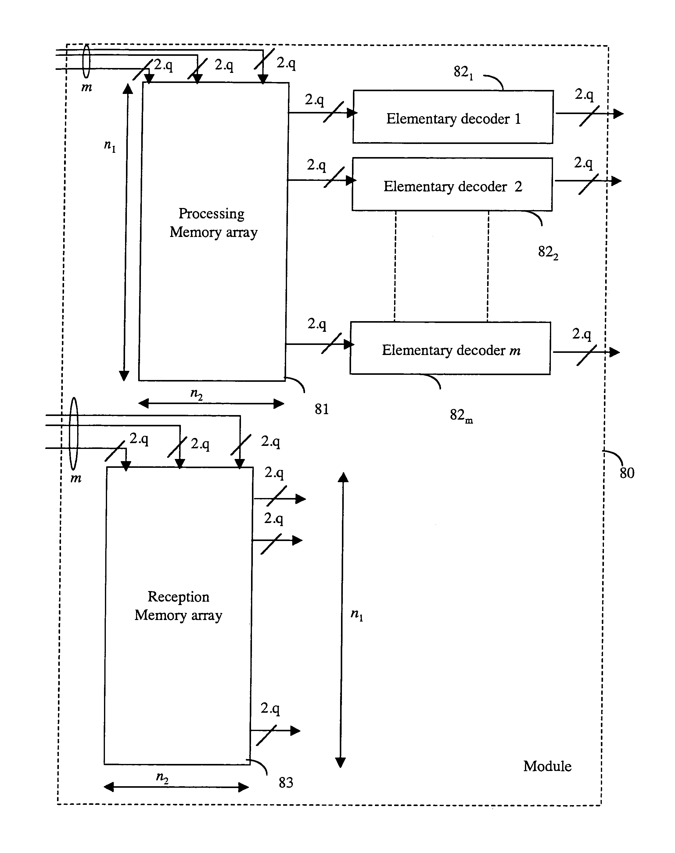
[0084]Thus, the invention relies on a wholly novel and inventive approach to decoding in which, in a module, the number of decoders is duplicated without duplicating the number of storage means. This amounts to an advantage over the prior art where those skilled in the art naturally duplicate the number of memories and decoders to increase the throughput rates while it is the memory that takes up the greatest amount of space in a decoding circuit (for example, the memory can take up 80% of the total surface area of the circuit).
[0113]Thus, the invention is advantageously used in the context of “turbo-codes” which especially provide high performance in terms of residual error rate after decoding.

Problems solved by technology

A major drawback of this prior art technique is that it introduces high latency into data processing, the latency being the number of samples that comes out of the decoder before a piece of data present at input is located, in its turn, at output.
Furthermore, space requirement of the circuit is itself also relatively great and increases with the number of modules.
The latency and space requirements parameters of the circuit constitute an essential defect when the number of iterations and / or the length of the code increase.
Nevertheless, a major drawback of this structure is that it leads to a reduction in the data throughput rate.
Other approaches (for example using shift registers) may be envisaged, but they take up more space.
As a trade-off, the cascade-connection of several modules leads to an increase in the latency and the amount of space taken up by the circuit.
These parameters soon constitute an essential defect when there is an increase in the number of iterations and / or the length of the code.
Other approaches (for example using shift registers) may be envisaged, but they take up more space.

Method used


Image

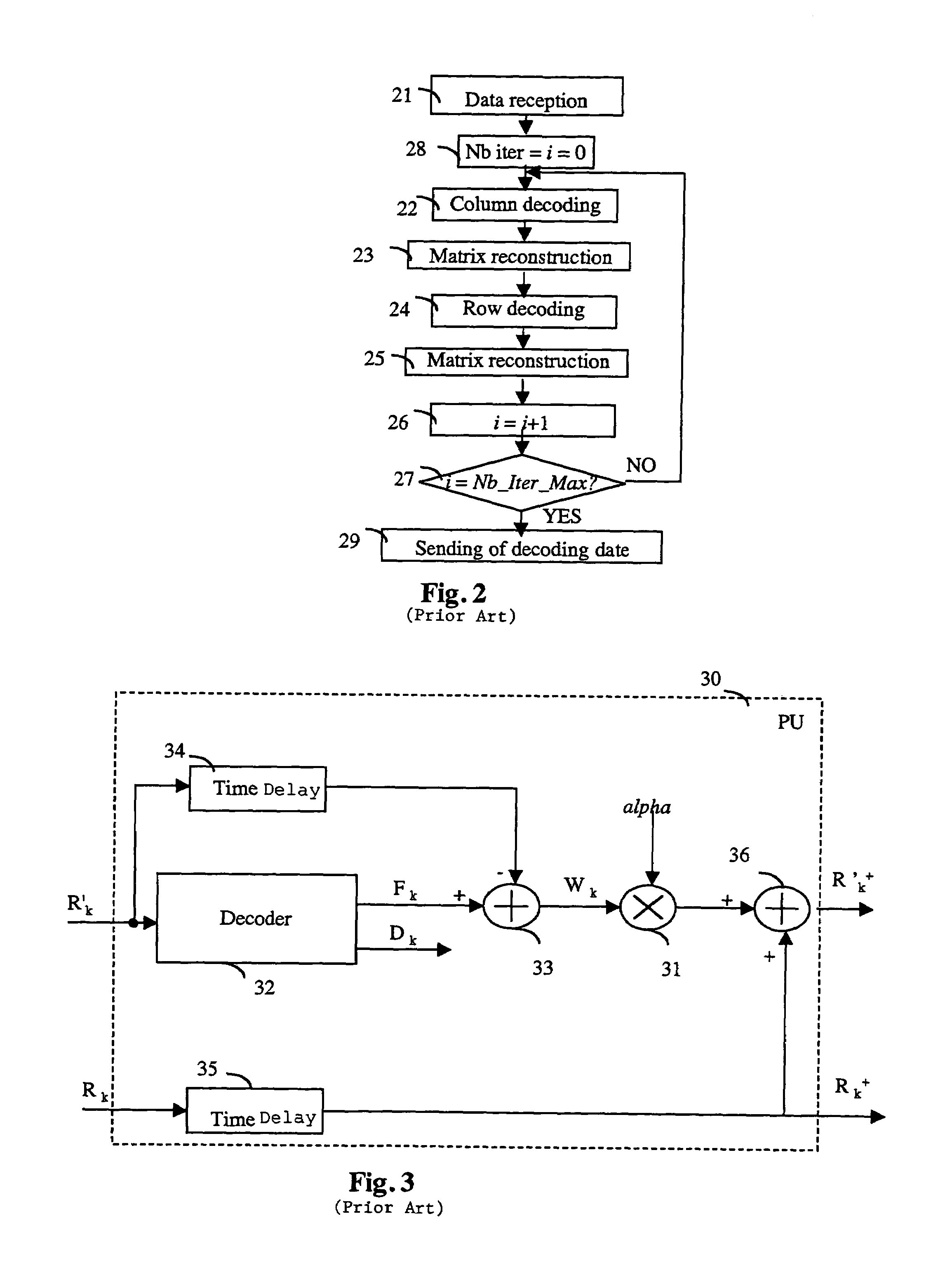
  • High-speed module, device and method for decoding a concatenated code
  • High-speed module, device and method for decoding a concatenated code
  • High-speed module, device and method for decoding a concatenated code

Examples


Embodiment Construction

[0127]The general principle of the invention relies on a particular architecture of the memories used in an operation of concatenated code decoding and more particularly the decoding of these codes.

[0128]The concatenated codes are decoded iteratively by decoding first of all each of the elementary codes along the rows and then each of the elementary codes along the columns.

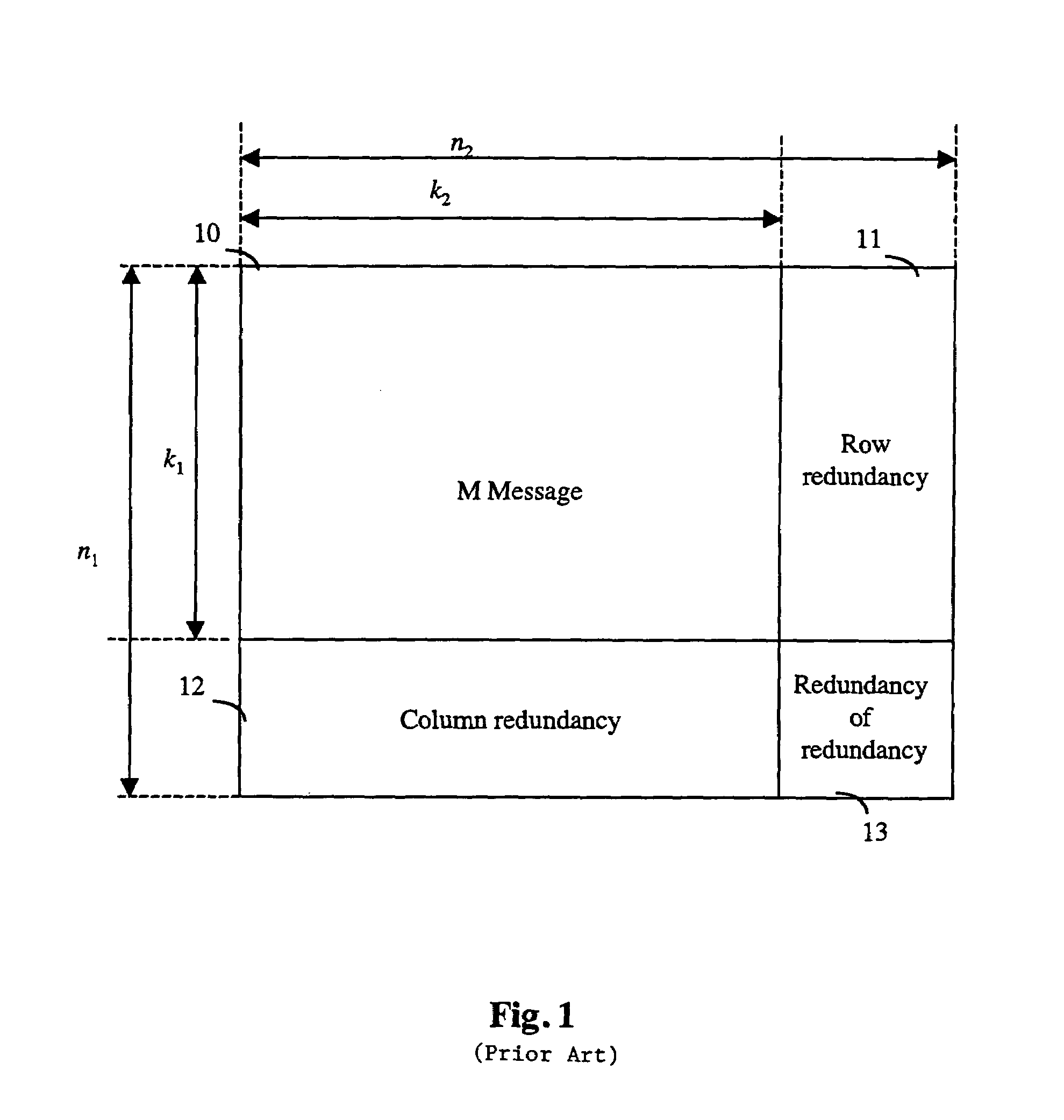
[0129]According to the invention, to improve the decoding bit rate, the elementary decoders are parallelized:[0130]to decode (see FIG. 1) the n1 rows, m1 (2≦m1≦n1) elementary decoders of the code C2 are used, and / or[0131]to decode the n2 columns, m2 (2≦m2≦n2) elementary decoders of the code C1 are used.

[0132]Each elementary decoder has input data coming from a reception and / or processing memory and gives output data that is kept in a reception and / or processing memory. In order to further improve the decoding throughput rate while maintaining a circuit clock speed that continues to be reasonable, several pieces of...


PUM


Abstract

The invention concerns a module for decoding a concatenated code, corresponding at least to two elementary codes C1 and C2, using storage means (81, 83, 90, 111, 113) wherein are stored samples of data to be decoded, comprising at least two elementary decoders (821, 822, . . . 82m) of at least one of the elementary codes, the elementary decoders associated with one of the elementary codes simultaneously processing, in parallel separate code words contained in the storage means.

Description

CROSS-REFERENCE TO RELATED APPLICATION[0001]This Application is a Section 371 National Stage Application of International Application No. PCT / FR01 / 03509 filed Nov. 9, 2001 and published as WO 02 / 39587 on May 16, 2002, not in English.FIELD OF THE INVENTION[0002]The field of the invention is that of the encoding of digital data belonging to one or more sequences of source data to be transmitted, or broadcast, especially in the presence of noises of various sources, and of the decoding of the encoded data thus transmitted.[0003]More specifically, the invention relates to an improvement in the technique of the decoding of codes known especially as “turbo-codes” (registered trademark), and more particularly the operation for the iterative decoding of concatenated codes.BACKGROUND OF THE INVENTION[0004]The transmission of information (data, images, speech, etc) increasingly relies on digital transmission techniques. A great deal of effort has been made in source encoding to reduce the dig...

Claims


Application Information

Patent Timeline
IPC IPC(8): H03M13/29G06F11/10
CPCH03M13/2963H03M13/6566H03M13/6577H03M13/29
Inventor ADDE, PATRICKPYNDIAH, RAMESH
Owner FRANCE TELECOM SA
Learn More