Control stability system for moist air dehumidification units and method of operation

a technology of stability system and moist air, which is applied in the direction of defrosting, heating types, domestic cooling apparatus, etc., can solve the problems of reducing the quantity of refrigeration available in the remainder of the refrigerant system to achieve dehumidification, affecting the efficiency of dehumidification, etc., to achieve efficient dehumidification, maximum capacity and efficiency, and accumulation

Active Publication Date: 2007-05-22
JOHNSON CONTROLS TYCO IP HLDG LLP
View PDF37 Cites 49 Cited by
  • Summary
  • Abstract
  • Description
  • Claims
  • Application Information

AI Technical Summary

Benefits of technology

[0012]An advantage of the present invention is that refrigerant is not inadvertently trapped in the inactivated circuit, but is initially moved from the inactivated circuit into the activated circuit, and then is metered from the activated circuit back to the inactivated circuit based on sensed environmental conditions that exceed predetermined limits. In this way, the proper amount of excess refrigerant can be moved into the inactivated circuit. Stated alternatively, the proper amount of refrigerant is metered into the active circuit based on sensed environmental or operating conditions in the active circuit.
[0013]Another advantage of the present invention is that, by using the inactivated circuit for storage of the excess or unneeded refrigerant, the accumulator can be eliminated.
[0014]Another advantage of the present invention is that by adjusting the amount of refrigerant in the activated circuit, proper system control can be maintained. Specifically, the compressor pressure range for maximum capacity and efficiency can be maintained. The refrigerant evaporation temperature, which is related to the pressure, also can be controlled for efficient dehumidification. This translates to energy savings for the operator or owner.
[0015]A related advantage to maintaining compressor operational pressures within design pressures and avoiding the fluctuations in pressure that occur as a result of excess refrigerant is extended compressor life. Premature compressor failure as a result of events such as slugging can be avoided.

Problems solved by technology

As the outdoor temperature falls, the amount of refrigerant that becomes trapped in the condenser coil will increase, resulting in a drop in the quantity of refrigeration available in the remainder of the refrigerant system to accomplish dehumidification.
Without adequate refrigerant in the dehumidification circuit, operational problems will occur with the air delivery system.
The refrigerant can become trapped in the condenser coil, and if switching is required to the cooling mode, additional refrigerant can be trapped in the reheat circuit.
One of the problems is decreased system capacity as the refrigerant normally available in a properly operating system is trapped in the condenser coil and not available to the compressor.
Associated with this problem is inadequate suction pressure at the compressor, since the gas refrigerant that normally is available to the compressor from the evaporator is trapped as a liquid in the condenser.
However, it fails to address the problem of refrigerant being drawn into the activated circuit.
One of these problems is unacceptable discharge pressures from the compressor, which can lead to decreased system efficiency.
If the amount of excess refrigerant drawn into the activated circuit is too great, slugging can also be a problem.
These operational problems can result in a severe reduction in compressor life, and in the worst circumstances, to premature compressor failure.

Method used


Image

  • Control stability system for moist air dehumidification units and method of operation
  • Control stability system for moist air dehumidification units and method of operation
  • Control stability system for moist air dehumidification units and method of operation

Examples


Embodiment Construction

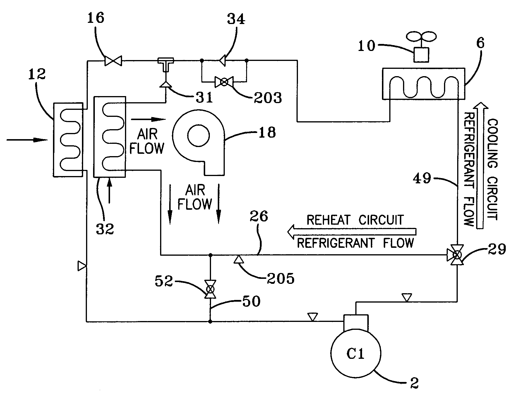
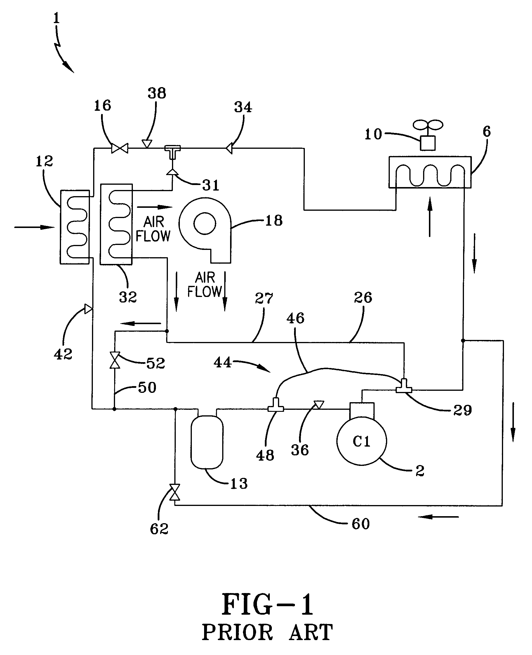
[0022]FIG. 1 illustrates a prior art single compressor circuit. This system is set forth in United Stated Patent Application No. U.S. 2004 / 0089015 A1, based on U.S. Ser. No. 10 / 694,316 to Knight et al., filed Oct. 27, 2003, now allowed, (“the Knight application”) and assigned to the assignee of the present invention, which allowed application is incorporated herein by reference. This system includes a reheat circuit and a cooling circuit which operate independently. In operation, the prior art system of FIG. 1 includes the usual components of a cooling system circuit, a compressor 2, connected by conduit to a condenser 6 which is connected by conduit to an evaporator 12, which is connected by conduit to compressor 2. In the cooling mode, refrigerant sealed in system 1 is compressed into a hot, high-pressure gas in compressor 2 and flows through conduit to condenser 6. The condenser having a heat exchanger or coil 6, includes a fan 10 which blows air across the condenser coil 6. In t...


PUM


Abstract

A system and humidity control method is provided for a multi-stage cooling system having two or more refrigerant circuits that balances humidity control and cooling demand. Each refrigerant circuit includes a compressor, a condenser and an evaporator. A hot gas reheat circuit having a hot gas reheat coil is connected to one of the refrigerant circuits and is placed in fluid communication with the output airflow from the evaporator of that refrigerant circuit to provide additional dehumidification to the air when humidity control is requested. The hot gas reheat circuit bypasses the condenser of the refrigerant circuit during humidity control. Humidity control is performed during cooling operations and ventilation operations. During a first stage cooling operation using only one refrigerant circuit and having a low cooling demand, the request for humidity control activates the hot gas reheat circuit for dehumidification and activates a second refrigerant circuit to provide cooling capacity. The hot gas reheat circuit is sized to match the cooling provided by the evaporator so that air cooled by passing through the evaporator can be reheated. Excess refrigerant is passed into the inactive cooling circuit so that proper pressure and temperature can be maintained in the active reheat circuit and so that high head pressure that can damage the compressor can be avoided. During a second stage cooling operation using two or more refrigerant circuit and having a high cooling demand, the request for humidity control is suspended and is initiated only upon the completion of the second stage cooling demand.

Description

FIELD OF THE INVENTION [0001]The present invention relates generally to controlling refrigerant flow into an air conditioning system having a hot gas reheat circuit, and specifically for controlling the amount of refrigerant flowing into the reheat circuit based on outdoor and indoor ambient conditions.BACKGROUND OF THE INVENTION[0002]Air delivery systems, such as used in commercial applications, typically are systems that can be used to cool or to accomplish dehumidification when ambient conditions are such that there is no demand for cooling. This demand for dehumidification can often occur on days when the temperature is cool and there is a high humidity level, such as damp, rainy spring and fall days. Under such conditions, it may be necessary to switch the operation of the air delivery system from cooling mode to dehumidification mode.[0003]When switching an air delivery system, such as are used in commercial applications, from the cooling mode to the dehumidification mode in a...

Claims


Application Information

Patent Timeline
Patent Type & Authority Patents(United States)
IPC IPC(8): F25D25/00
CPCF24F3/153F25B41/04F25B2400/0403
Inventor WEBER, NATHAN ANDREWKNIGHT, JOHN TERRYPICKLE, STEPHEN BLAKE
Owner JOHNSON CONTROLS TYCO IP HLDG LLP
Why Eureka
Try Eureka