Piezoelectric accelerometer

a piezoelectric accelerometer and accelerometer technology, applied in the field of piezoelectric accelerometers, can solve the problems of insufficient voltage produced by the accelerometer, inability to use, and relatively high acceleration, and achieve the effects of low cost, high sensitivity and reliability

Inactive Publication Date: 2007-05-22
LAU MICHAEL PING CHEUNG
View PDF4 Cites 4 Cited by
  • Summary
  • Abstract
  • Description
  • Claims
  • Application Information

AI Technical Summary

Benefits of technology

[0005]It is therefore an object of the present invention to eliminate the foregoing drawbacks in the prior art and provide a low cost piezoelectric accelerometer with high sensitivity and reliability while no wire or solder is required on the piezoelectric element thereof.
[0006]In order to realize the above object, the present invention provides a piezoelectric accelerometer comprising a housing with two complementary parts whereby forming a chamber in which a metal mass, an abutting piezoelectric element movably mounted in place and two conductive contact elements are provided, characterized in that: the metal mass is in intimate contact with the piezoelectric element for improving the efficiency and sensitivity thereof and both of which are sandwiched in an elastic manner between the two conductive contact elements acting as the electric terminals for connecting the accelerometer to any external electronic circuit for further processing, thereby no adhesive, wire or solder is required.

Problems solved by technology

A disadvantage thereof is that the mass of such a piezoelectric element is relatively small, thereby the voltage produced therefrom is inadequate for further processing and a relatively high acceleration is required.
Further, the heat from soldering of the wires and the size of the solder joints could adversely affect the characteristics of the piezo and such an accelerometer can be only used at temperature lower than the melting point of the solder, thereby it is unreliable and of limited use.

Method used


Image

  • Piezoelectric accelerometer
  • Piezoelectric accelerometer
  • Piezoelectric accelerometer

Examples


Embodiment Construction

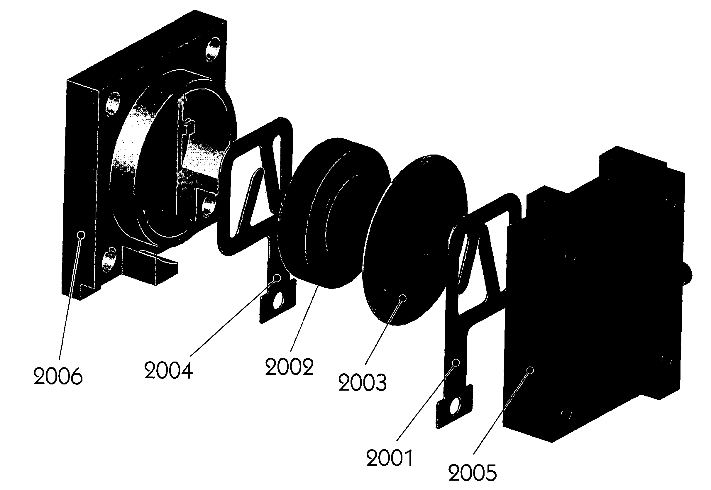
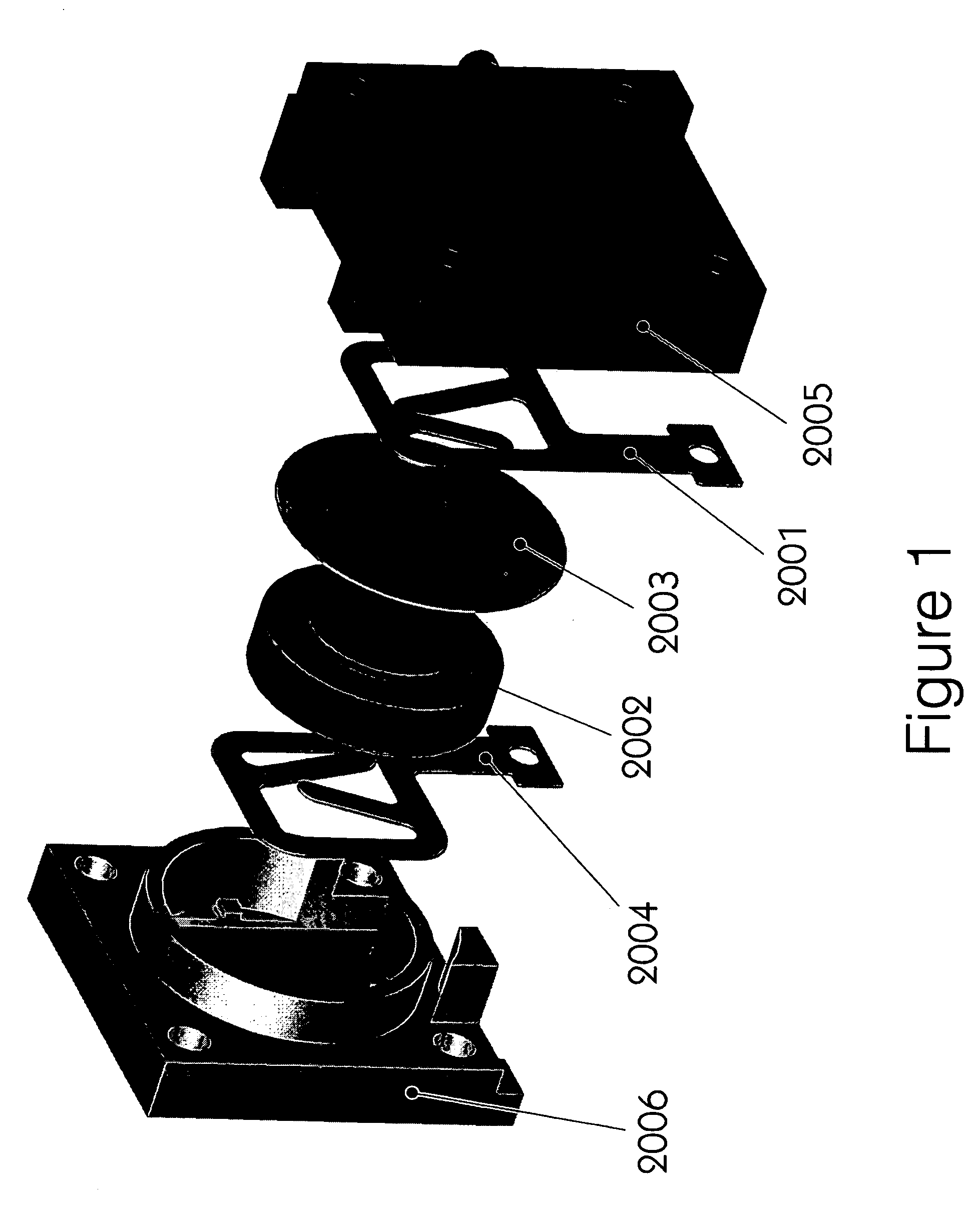
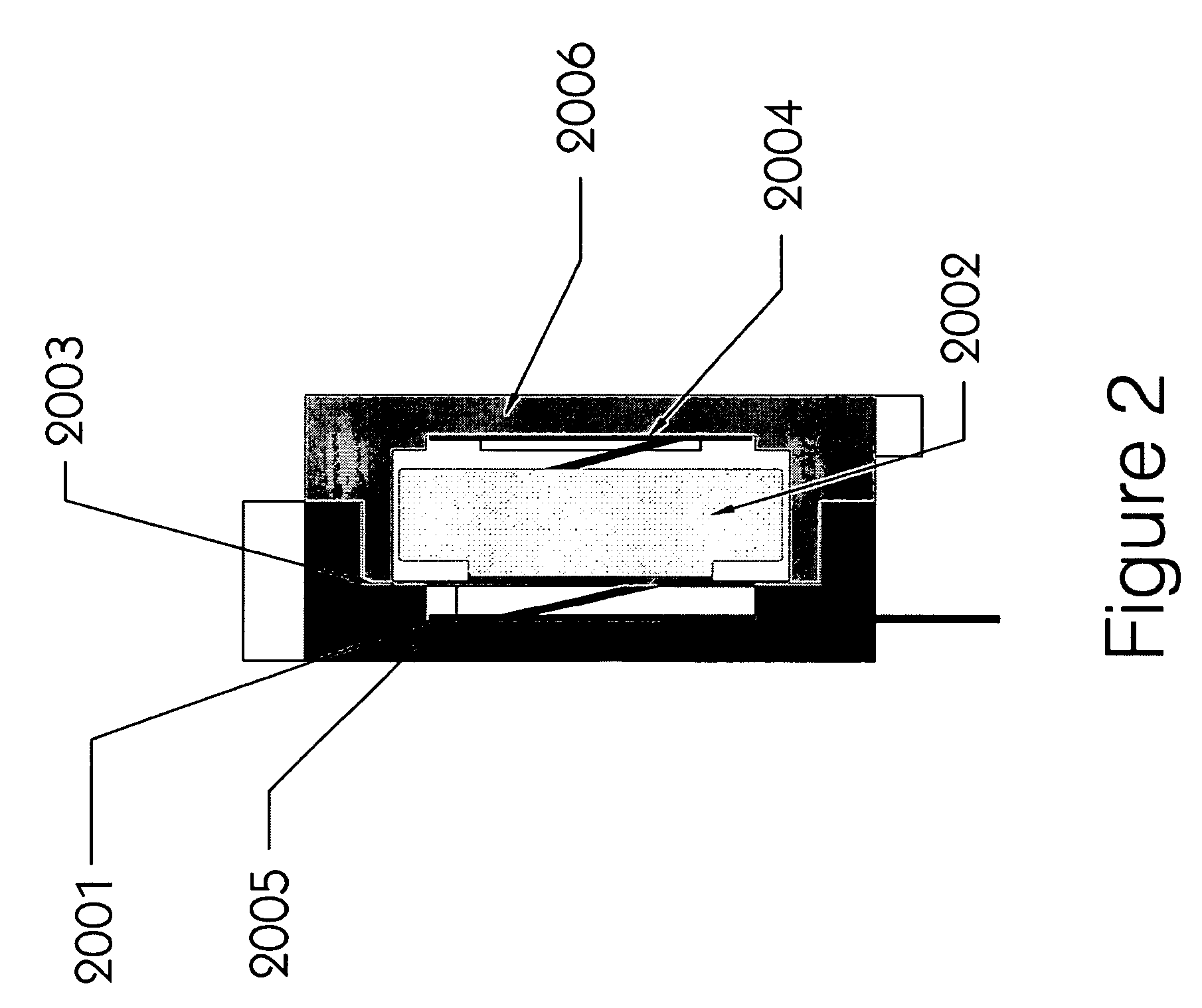
[0013]FIG. 1 and FIG. 2 respectively illustrate a stereoscopic exploded and sectional view of an embodiment of the present invention. According to the embodiment of present invention, the accelerometer comprises a plastic housing having two complementary parts (2005, 2006) joined together by means of screws and / or adhesive, thereby forming a chamber in which a metal mass (2002) and an abutting piezoelectric element (2003) movably mounted in place being sandwiched in an elastic manner between two conductive contact elements (2001, 2004) which are in turn firmly mounted in respective part (2005, 2006) of the housing.

[0014]In this embodiment, the housing is made of plastic material for the cost-effectiveness thereof. Alternatively, it can adaptively be made of other suitable materials with a much higher melting point for higher temperature applications.

[0015]Wherein the piezoelectric element (2003) is mounted movably in place in such a manner that it will only displace slightly in an e...


PUM


Abstract

A piezoelectric accelerometer comprising a housing with two complementary parts (2005, 2006) in which a metal mass (2002) and an abutting piezoelectric element (2003) movably mounted in place are sandwiched between two conductive contact elements (2001, 2004), wherein the metal mass (2002) is in intimate contact with the piezoelectric element (2003) and the two conductive contact elements (2001, 2004) act as the electric terminals for connecting the accelerometer to any external electronic circuit for further processing.

Description

CROSS-REFERENCE TO RELATED APPLICATION[0001]This application claims the benefit of U.S. Provisional application No. 60 / 653,519, filed Feb. 17, 2005.FIELD OF THE INVENTION[0002]The present invention relates to an accelerometer, in particular a low cost piezoelectric accelerometer with high sensitivity and simple means.BACKGROUND OF THE INVENTION[0003]It is well known that across the terminals of a piezoelectric element a voltage can be induced when a pressure is applied thereto. In this connection, a basic piezoelectric accelerometer can be further constituted by comprising a piezoelectric element to which two wires being soldered whereby forming the terminals for connection with an electronic signal processing circuit for further processing; and a housing having a chamber in which the piezoelectric element is mounted. A disadvantage thereof is that the mass of such a piezoelectric element is relatively small, thereby the voltage produced therefrom is inadequate for further processin...

Claims


Application Information

Patent Timeline
Patent Type & Authority Patents(United States)
IPC IPC(8): G01P15/09H01L41/22
CPCG01P1/023G01P15/0907
Inventor LAU, MICHAEL PING CHEUNG
Owner LAU MICHAEL PING CHEUNG
Why Eureka
Try Eureka