
Cycloidal hybrid advanced surface effects vehicle

a surface effect and hybrid technology, applied in the field of aerial vehicles, can solve the problems of prohibitive maintenance and fuel costs, limited payload size, and significant time required to transport cargo by sea for long distances, and achieve the effects of maximizing vehicle lift, reducing drag, and increasing lift capability

Inactive Publication Date: 2007-05-22
BOSCHMA RES
View PDF22 Cites 19 Cited by
  • Summary
  • Abstract
  • Description
  • Claims
  • Application Information

AI Technical Summary

Benefits of technology

"The present invention is an aerial vehicle that includes a fuselage with two pods that are positioned parallel to each other and an equal distance from the plane of symmetry. The vehicle also includes two cylindrical-shaped cycloidal propulsion units that are positioned between the two pods and are oriented perpendicular to the plane of symmetry. The vehicle also has a cargo container that is positioned between the two pods and is oriented aft of the forward cycloidal propulsion unit. The two cycloidal propulsion units can be controlled to operate in three modes: curtate, prolate, and fixed-wing. The fixed-wing mode uses the thrust provided by the thruster units to propel the vehicle forward. The vehicle can also use the thruster units to assist in turning and maintain directional control during flight. The vehicle flies close to the earth's surface and maximizes lift and minimizes drag by incorporating a lighter-than-air gas in the interior chambers of the fuselage and controlling the propulsion units in conjunction with the wing-in-ground-effect."

Problems solved by technology

Also, the time required to transport cargo by sea for long distances can be significant.
In the case of large cargo-carrying aircraft, the size of the payload is limited.
With this as a limitation, the costs to operate such aircraft (e.g. maintenance and fuel costs) can be prohibitive.
The air transport of cargo, however, is relatively fast.
Although many of these solutions are effective at controlling “pitch up,” many also increase the vehicle weight which adversely impacts both fuel efficiency and power.

Method used


Image

  • Cycloidal hybrid advanced surface effects vehicle
  • Cycloidal hybrid advanced surface effects vehicle
  • Cycloidal hybrid advanced surface effects vehicle

Examples


Embodiment Construction

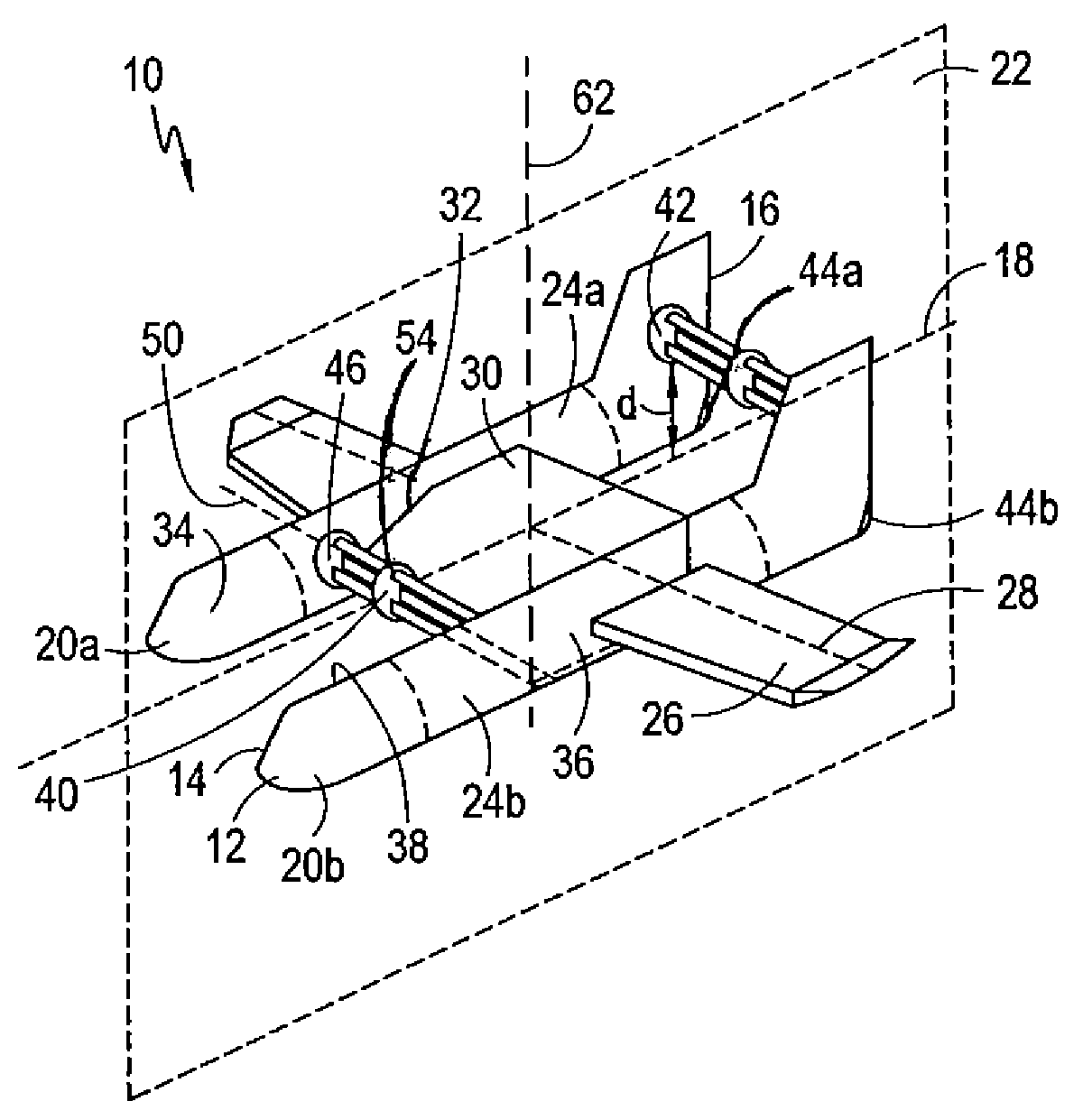
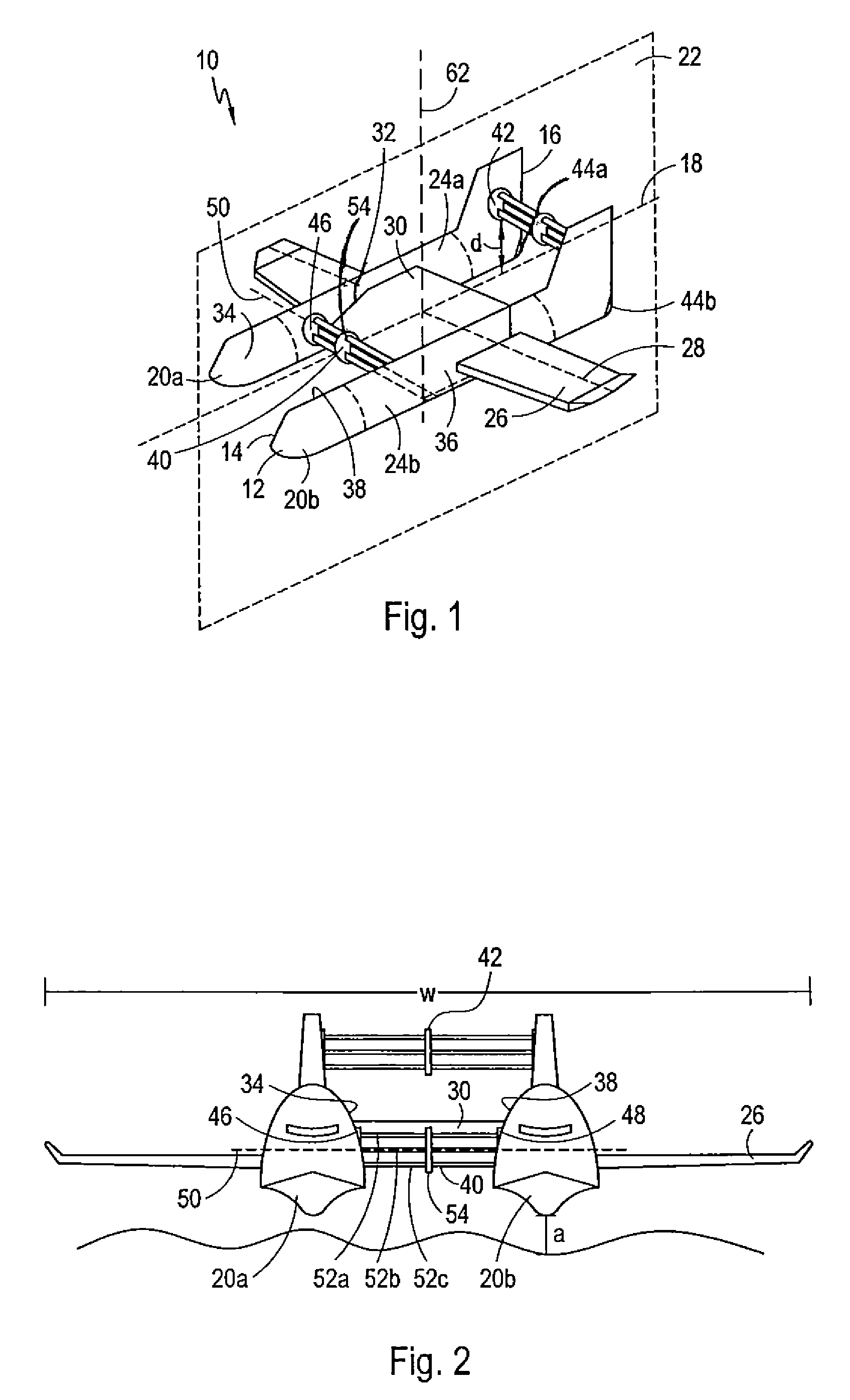
[0021]Referring initially to FIG. 1, an aerial vehicle in accordance with the present invention is shown and is generally designated 10. As shown, the vehicle 10 includes a fuselage 12 having a forward end 14 and an aft end 16. Further, the fuselage 12 defines a longitudinal axis 18. Preferably, the fuselage 12 is comprised of two elongated pods, of which pods 20a and 20b are exemplary. As shown, pod 20a is juxtaposed with and parallel to pod 20b. Also, the two pods 20a and 20b are substantially parallel to a plane of symmetry 22 containing the longitudinal axis 18. As contemplated by the present invention, pod 20a and pod 20b are positioned on either side of the plane of symmetry 22, and they are spaced an equal distance from the plane of symmetry 22. As shown in phantom in FIG. 1, pod 20a and pod 20b are each formed with an interior chamber, chambers 24a and 24b respectively, for receiving and containing a lighter-than-air gas such as helium.

[0022]Still referring to FIG. 1, the ve...


PUM


Abstract

A “wing in ground effect” aerial vehicle includes a wing mounted on a fuselage, and two cycloidal propulsion units for providing lift, thrust and longitudinal control. Additional lift is provided by a lighter-than-air gas such as helium contained in the fuselage. Operationally, the two cycloidal propulsion units and the volume of lighter-than-air gas are concertedly regulated to achieve “wing in ground effect” flight. Importantly, the two cycloidal propulsion units may operate in one of several modes, to include a curtate mode, a prolate mode, and a fixed-wing mode. Additionally, the vehicle may hover. Also, a thruster unit is mounted on the fuselage for providing forward thrust in combination with, or in lieu of, the two cycloidal propulsion units.

Description

FIELD OF THE INVENTION[0001]The present invention pertains generally to aerial vehicles. More particularly, the present invention pertains to “wing in ground effect” aerial vehicles. The present invention is particularly, but not exclusively, useful as a “wing in ground effect” aerial vehicle having a plurality of cycloidal propulsion units for providing thrust, lift and longitudinal stability.BACKGROUND OF THE INVENTION[0002]Traditionally, the long-range transport of civilian and military cargo has been accomplished by either sea lift assets or large cargo-carrying aircraft. In the case of ocean-going vessels, large port facilities are required. Also, the time required to transport cargo by sea for long distances can be significant. In the case of large cargo-carrying aircraft, the size of the payload is limited. With this as a limitation, the costs to operate such aircraft (e.g. maintenance and fuel costs) can be prohibitive. The air transport of cargo, however, is relatively fast...

Claims


Application Information

Patent Timeline
Patent Type & Authority Patents(United States)
IPC IPC(8): B64C17/08B64C27/22
CPCB60V1/08B60V3/06B64C11/006B64C39/005B64C39/04B64C35/00B64B2201/00B64U10/30B64U30/10B64U2101/60
Inventor BOSCHMA, JR., JAMES H.MCNABB, MICHAEL
Owner BOSCHMA RES
Learn More