Stent with protruding branch portion for bifurcated vessels

a branch portion and stent technology, applied in the field of medical stents, can solve the problems of compromising the benefit of stent usage to the patient, struts and connecting members may block the use of post-operative devices to treat a branch vessel, and limited success rate,

Inactive Publication Date: 2007-05-22
BOSTON SCI SCIMED INC
View PDF511 Cites 180 Cited by
  • Summary
  • Abstract
  • Description
  • Claims
  • Application Information

AI Technical Summary

Benefits of technology

[0015]In one embodiment, the second pattern is configured according to the first pattern having at least one absent connector, and in another embodiment, the second pattern has a plurality of absent connectors. The second pattern may have second pattern struts, and the second pattern struts can be more densely packed than the first pattern struts.

Problems solved by technology

Conventional stents have been used for treating more complex vascular problems, such as lesions at or near bifurcation points in the vascular system, where a secondary artery branches out of a larger, main artery, with limited success rates.
Furthermore, the configuration of struts and connecting members may obstruct the use of post-operative devices to treat a branch vessel in the region of a vessel bifurcation.
Accordingly, the use of regular stents to treat diseased vessels at or near a vessel bifurcation may create a risk of compromising the benefit of stent usage to the patient after the initial procedure and in future procedures on the main vessel, branch vessels, and / or the bifurcation point.
Regular stent design has typically compromised one consideration for the other in an attempt to address both.
Although conventional stents are routinely used in clinical procedures, clinical data shows that these stents are not capable of completely preventing in-stent restenosis (ISR) or restenosis caused by intimal hyperplasia.
Patients treated with coronary stents can suffer from in-stent restenosis.
However, success with the systemic approach has been limited.
Systemic delivery of drugs is inherently limited since it is difficult to achieve constant drug delivery to the inflicted region and since systemically administered drugs often cycle through concentration peaks and valleys, resulting in time periods of toxicity and ineffectiveness.
Although prior art references disclose numerous stents configurations coated with one or more distinct anti-restenosis agents, they do not disclose the inventive stent design of the present application.
This is particularly true in complicated cases, such as lesions located at a bifurcation.

Method used


Image

  • Stent with protruding branch portion for bifurcated vessels
  • Stent with protruding branch portion for bifurcated vessels
  • Stent with protruding branch portion for bifurcated vessels

Examples


Embodiment Construction

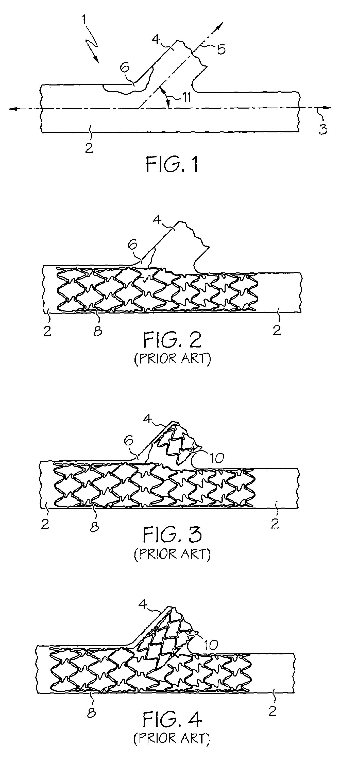
[0044]The present invention relates to stents for placement at vessel bifurcations and are generally configured to at least partially cover a portion of a branch vessel as well as a main vessel. Referring to FIG. 1, an exemplary blood vessel bifurcation 1 is shown, having a main vessel 2 extending along a main vessel axis 3 and a branch vessel 4 extending along a branch vessel axis 5. Main vessel 2 and branch vessel 4 are disposed at an angle 11 of less than 90 degrees. An obstruction 6 is located within bifurcation 1, spanning or at least partially obstructing main vessel 2 and a proximal portion branch vessel 4.

[0045]Prior attempts at relieving main vessel 2 and branch vessel 4 from obstruction 6, such as the one depicted in FIG. 1, have been problematic. Referring to FIGS. 2–4, examples of prior methods and structures for stenting an obstructed bifurcation are shown. As shown in FIG. 2, a first stent 8 is introduced into main vessel 2 and an access hole or side opening in the wal...


PUM


Abstract

The present invention is directed to a stent for use in a bifurcated body lumen having a main branch and a side branch. The stent comprises a radially expandable generally tubular stent body having proximal and distal opposing ends with a body wall having a surface extending therebetween. The surface has a geometrical configuration defining a first pattern, and the first pattern has first pattern struts and connectors arranged in a predetermined configuration. The stent also comprises a branch portion comprised of a second pattern, wherein the branch portion is at least partially detachable from the stent body.

Description

CROSS-REFERENCE TO RELATED APPLICATIONS[0001]The present application claims the benefit of U.S. Provisional Application No. 60 / 404,756, filed Aug. 21, 2002, U.S. Provisional Application No. 60 / 487,226, filed Jul. 16, 2003, and U.S. Provisional Application No. 60 / 488,006, filed Jul. 18, 2003, the entire contents of which are incorporated herein by reference.[0002]The present application is a continuation-in-part of now abandoned U.S. patent application Ser. No. 09 / 668,687, filed Sep. 22, 2000, which was a continuation-in-part of U.S. patent application Ser. No. 09 / 326,445, filed Jun. 4, 1999, which issued as U.S. Pat. No. 6,325,826. The present application is also a continuation-in-part of U.S. patent application Ser. No. 10 / 440,401, filed May 19, 2003 which is a continuation of U.S. patent application Ser. No. 09 / 750,372, filed Dec. 27, 2000, which issued as U.S. Pat. No. 6,599,316. The present application is also a continuation-in-part of U.S. patent application Ser. No. 09 / 963,114...

Claims


Application Information

Patent Timeline
Patent Type & Authority Patents(United States)
IPC IPC(8): A61F2/06A61F2/00A61F2/82
CPCA61F2/82A61F2/856A61F2/91A61F2/915A61F2/954A61F2/958A61M25/1002A61F2/064A61F2/07A61F2002/821A61F2002/91508A61F2002/91516A61F2002/91525A61F2002/91533A61F2002/91558A61F2002/91583A61F2250/0018A61F2250/0039A61F2250/0098A61M2025/1045
Inventor DAVIDSON, CHARLES J.VARDI, GIL M.WILLIAMS, ERICYADIN, AMNONMORIK, YOSSIKONSTANTINO, EITANFELD, TANHUM
Owner BOSTON SCI SCIMED INC
Why Eureka
Try Eureka