Molded foam vehicle energy absorbing device and method of manufacture

a technology of energy absorption device and molded foam, which is applied in the direction of bumpers, manufacturing tools, vehicular safety arrangements, etc., can solve the problems of increasing the cost of finished parts, increasing the cost of foam bead materials, and long mold cycle time, so as to reduce the cost of base materials and reduce the mold cycle time. , the effect of less cos

Inactive Publication Date: 2007-05-22
CADILLAC PRODS AUTOMOTIVE
View PDF31 Cites 13 Cited by
  • Summary
  • Abstract
  • Description
  • Claims
  • Application Information

AI Technical Summary

Benefits of technology

[0010]Advantages of the present invention include a foam impact absorbing material formed by an injection molding or an extrusion process, which produces a less costly part from less costly base materials. By selectively cooling the mold used to form the part(s), and controlling part wall thickness and geometry, mold cycle time is reduced from about ten minutes for previous non-foam injection molded parts to about one minute.

Problems solved by technology

For example, the foam bead material is expensive, thereby increasing the finished part cost.
Due to the amount of time required to first melt all of the bead material and subsequently to cool both the foam material and the mold, mold cycle time is long, up to about ten minutes or longer.
Lengthy mold cycle time further increases the per part cost and decreases production efficiency.
This process is suitable for use in open, simple part molds, but may not be suitable to form complex geometric part shapes because the expanding foam may not enter or fill all cavities of the mold.
There are also limitations in the foams made in this manner due to the inherent material and process limitations.
Several drawbacks exist, however, for current energy absorbing components formed using the injection molding process.
Non-foam polymer material has been used in known energy absorbing components due to previous problems with processing foam material.
These “thin walled” components often transfer too much bumper impact energy to the vehicle or crush / distort without absorbing sufficient impact energy.

Method used


Image

  • Molded foam vehicle energy absorbing device and method of manufacture
  • Molded foam vehicle energy absorbing device and method of manufacture
  • Molded foam vehicle energy absorbing device and method of manufacture

Examples


Embodiment Construction

[0020]The following description of the preferred embodiments is merely exemplary in nature and is in no way intended to limit the invention, its application, or uses.

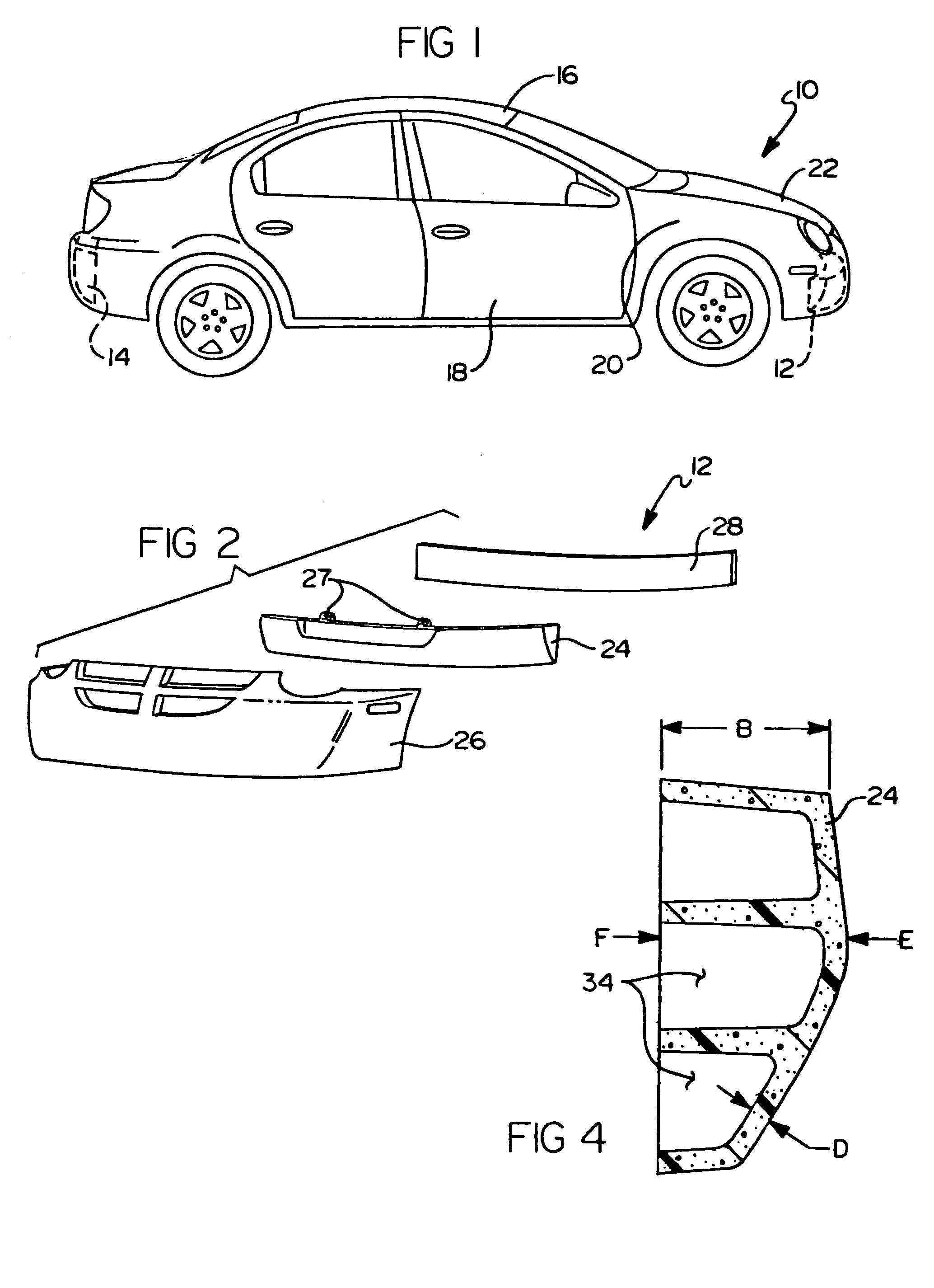
[0021]As best seen in FIG. 1, according to a preferred embodiment of the present invention, a molded foam vehicle energy absorbing system 10 can be applied to various locations including a front bumper 12 and a rear bumper 14 of a vehicle 16. In alternate embodiments of the present invention, the molded foam vehicle energy absorbing system 10 of the present invention can also be used in a door panel 18, a body panel 20, or a hood 22 of vehicle 16.

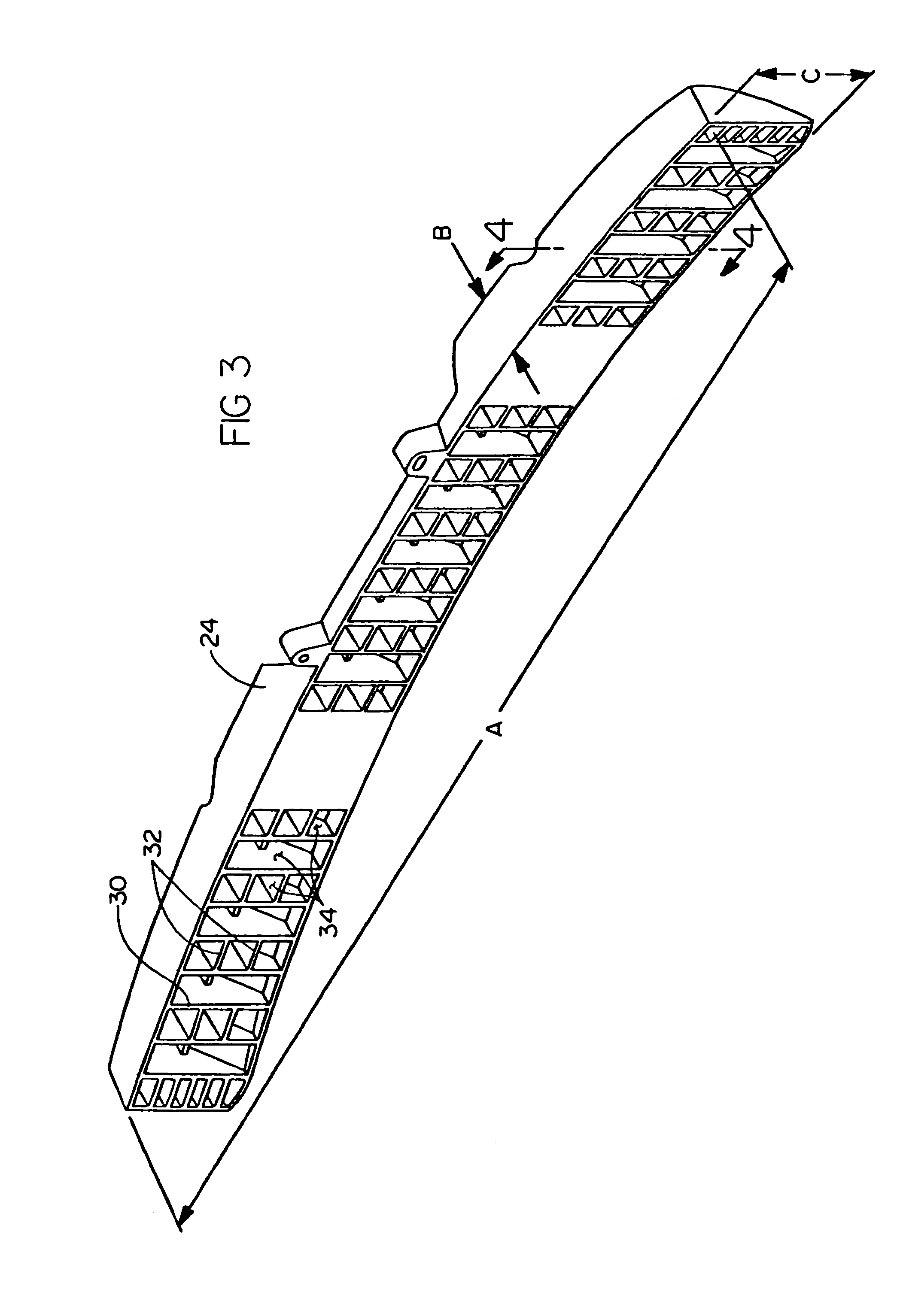
[0022]As seen in FIG. 2 in the preferred embodiment, a foam member 24 is formed and shaped to be inserted and / or received within a bumper fascia 26. In the embodiment shown, bumper fascia 26 having foam member 24 inserted therein, is supported from a bumper plate 28 of front bumper 12. Foam member 24 is retained within bumper fascia 26 by friction fit in close conformity to the...


PUM

PropertyMeasurementUnit
timeaaaaaaaaaa
injection timeaaaaaaaaaa
thicknessesaaaaaaaaaa

Abstract

A method for forming energy absorbing components for motor vehicles includes mixing a polymeric resin and blowing agent combination. The combination is heated to liquefy it. A mold for receiving the liquefied combination is cooled. The liquefied combination is injected into the mold in less than 1.5 seconds and preferably in 0.5 seconds or less.

Description

CROSS-REFERENCE TO RELATED APPLICATIONS[0001]This application is a continuation-in-part of U.S. patent application No. 10 / 691,366 filed on Oct. 22, 2003. The disclosure of the above application is incorporated herein by reference.FIELD OF THE INVENTION[0002]The present invention relates generally to energy absorption devices and more specifically to a device and method for forming a molded foam automotive bumper insert.BACKGROUND OF THE INVENTION[0003]Modern automotive bumpers are commonly designed to meet impact load standards such that the bumper absorbs an impact energy (typically the energy transferred by a 5 mph impact of the vehicle with an object) without damage to or activation of the vehicle's safety systems. These bumpers are typically formed using one or more metal plates, often having an energy absorbing material attached to the plate, or having a polymeric foam element acting as an energy absorbing material provided within one or more cavities of the bumper. Because the...

Claims


Application Information

Patent Timeline
Patent Type & Authority Patents(United States)
IPC IPC(8): B29C44/02B29C44/34B29C44/42B29C44/60B60R19/18
CPCB29C44/3419B29C44/421B29C44/60Y10T428/24496Y10T29/4998Y10T29/49885B60R2019/1833Y10T428/249953
Inventor ZANDER, ROBERT JKUCEJKO, RICHARDWILLIAMS, II, MICHAEL P
Owner CADILLAC PRODS AUTOMOTIVE
Why Eureka
Try Eureka