Biconical antenna

a biconical antenna and antenna technology, applied in antennas, antenna feed intermediates, electrical devices, etc., can solve the problems of difficult to use the conventional biconical antenna, too large to attach to a notebook computer, and short distance over which communication is possible in uwb communication

Active Publication Date: 2007-05-22
GIT JAPAN
View PDF11 Cites 19 Cited by
  • Summary
  • Abstract
  • Description
  • Claims
  • Application Information

AI Technical Summary

Benefits of technology

[0011]Accordingly, the present invention provides a biconical antenna, which is made so small and light that it can be used as a wireless interface for computers or the like, and which is manufactured with high precision.
[0017]In a biconical antenna with this configuration, a dielectric member is filled between a feeder portion and a ground portion. Thus, if the relative permittivity of the filled dielectric member is larger than the relative permittivity of air, then the wavelength of the electromagnetic waves inside the dielectric member become shorter, so that the biconical antenna can be made smaller. The biconical antenna can be made lighter by making the feeder portion and the ground portion by forming a conductive film provided on the inner surface of the frustum-shaped cavities.
[0018]It is preferable that the height of the frustum-shaped feeder portion is higher than the height of the frustum-shaped ground portion. This is because it has been found through various simulations, that when the height of the frustum shaped of the feeder portion is higher than the height of the frustum shape of the ground portion, then the diameter of the columnar shape can be made smaller, which is suitable for making the biconical antenna more compact.
[0019]Furthermore, it is preferable that a biconical antenna in which the height of the frustum shaped of the feeder portion is higher than the height of the frustum shape of the ground portion further comprises, in the lower surface, a dielectric member formed in one piece with the columnar dielectric member and having a cylindrical cavity inside; and a ground reinforcement portion provided with a cylindrical cavity and made of a conductive film connected to the ground portion. This is because by making the frustum shape of the feeder portion higher than the frustum shape of the ground portion, the size of the ground portion becomes smaller than the size of the feeder portion, and the portion that the ground portion is smaller can be compensated by the ground reinforcement portion. It is preferable that a cavity is provided at the apex portion of the frustum shape constituting the feeder portion, and that a reflector is provided by forming a conductive film on the inner surface of the cavity.

Problems solved by technology

On the other hand, the distance over which communication is possible in UWB communication is short.
However, as far as the size of the biconical antenna is concerned, the length of the frustum-shaped lead line in the biconical antenna disclosed in JP H9-8550A is 25 cm, which is too large to attach it to a notebook computer.
Due to their size, it would be difficult to use the conventional biconical antennas disclosed in JP 2001-185942A and JP H9-8550A as a wireless interface for computers.

Method used


Image

  • Biconical antenna
  • Biconical antenna
  • Biconical antenna

Examples


working example 1

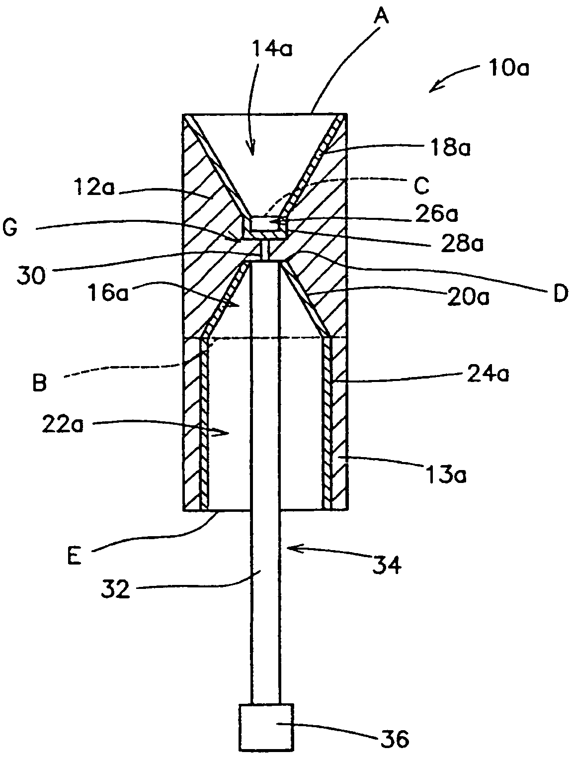
[0101]Working Example 1 relates to the case that the feeder portion 112a and the ground portion 114a have the same frustum shape, as shown in FIG. 12. The feeder portion 112a and the ground portion 114a have the same frustum shape, and are arranged coaxially but oriented in opposite directions, with the gap 16a arranged between them, thus forming a symmetrical shape. The bottom portions B and B′ of the frustum shapes both have a diameter of 15 mm, and the diameters of the apex portions A and A′ are both 2.4 mm, and their heights are both 13 mm. The apex portions A and A′ of the feeder portion 112a and the ground portion 114a are parallel to one another. The gap 106a is 1.5 mm. The relative permittivity of the dielectric member 118 is 3.6.

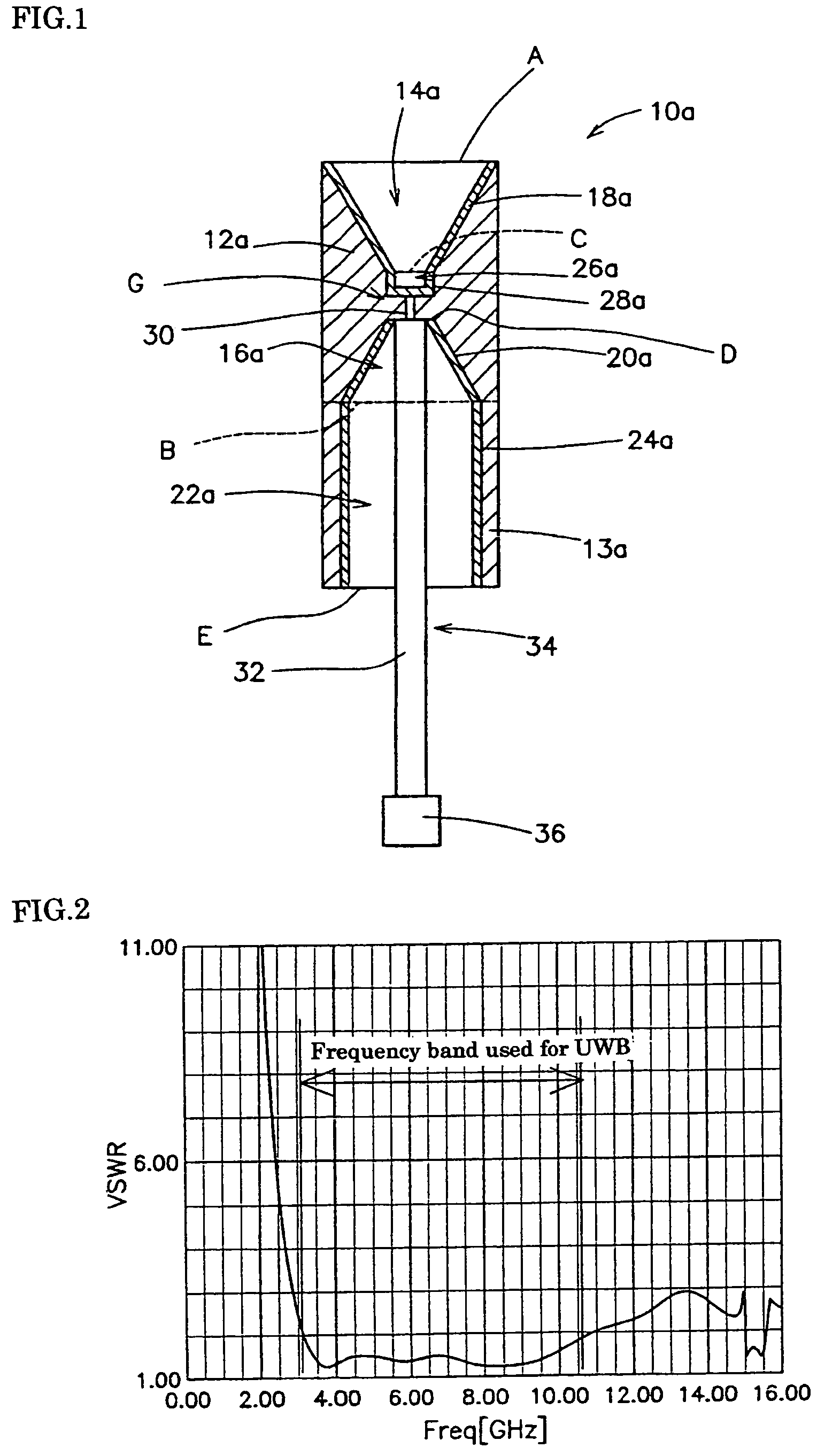
[0102]The following is a discussion of the simulation results for the biconical antenna shown in FIG. 12.

[0103]FIG. 13 is a graph showing the simulation result for Working Example 1 of a biconical antenna according to the second embodiment. In this ...

working example 2

[0117]Working Example 2 relates to the case that the shapes of the feeder portion 112b and the ground portion 114b are different.

[0118]FIG. 19 is a diagram showing the configuration of a biconical antenna in which the height of the feeder portion 112b is different from the height of the ground portion 114b. The height of the frustum-shaped feeder portion 112b is higher than the height of the frustum-shaped ground portion 114b. Moreover, the apex portion A of the feeder portion 112b is provided with a reflector 130b. The reflector 130b is disk-shaped. This reflector 130b has the function of smoothly cutting high-frequency components. It should be noted that a configuration without the reflector 130b is also possible. Furthermore, there is a ground reinforcement portion 128b that is connected to the bottom portion B′ of the ground portion 114b. The diameter of the bottom portion B′ of the ground portion 114b is the same as the diameter of the ground reinforcement portion 128b, for exa...

working example 3

[0131]Working Example 3 is based on the biconical antenna 110a of Working Example 1, and is provided with a reflector 130c.

[0132]FIG. 29 is a diagram showing the configuration of an antenna in which the biconical antenna 110a of Working Example 1 is provided with a reflector 130c. The reflector 130c is provided at the apex of the feeder portion 112c. The reflector 130c is disk-shaped. The height of the reflector 130c is 1 mm.

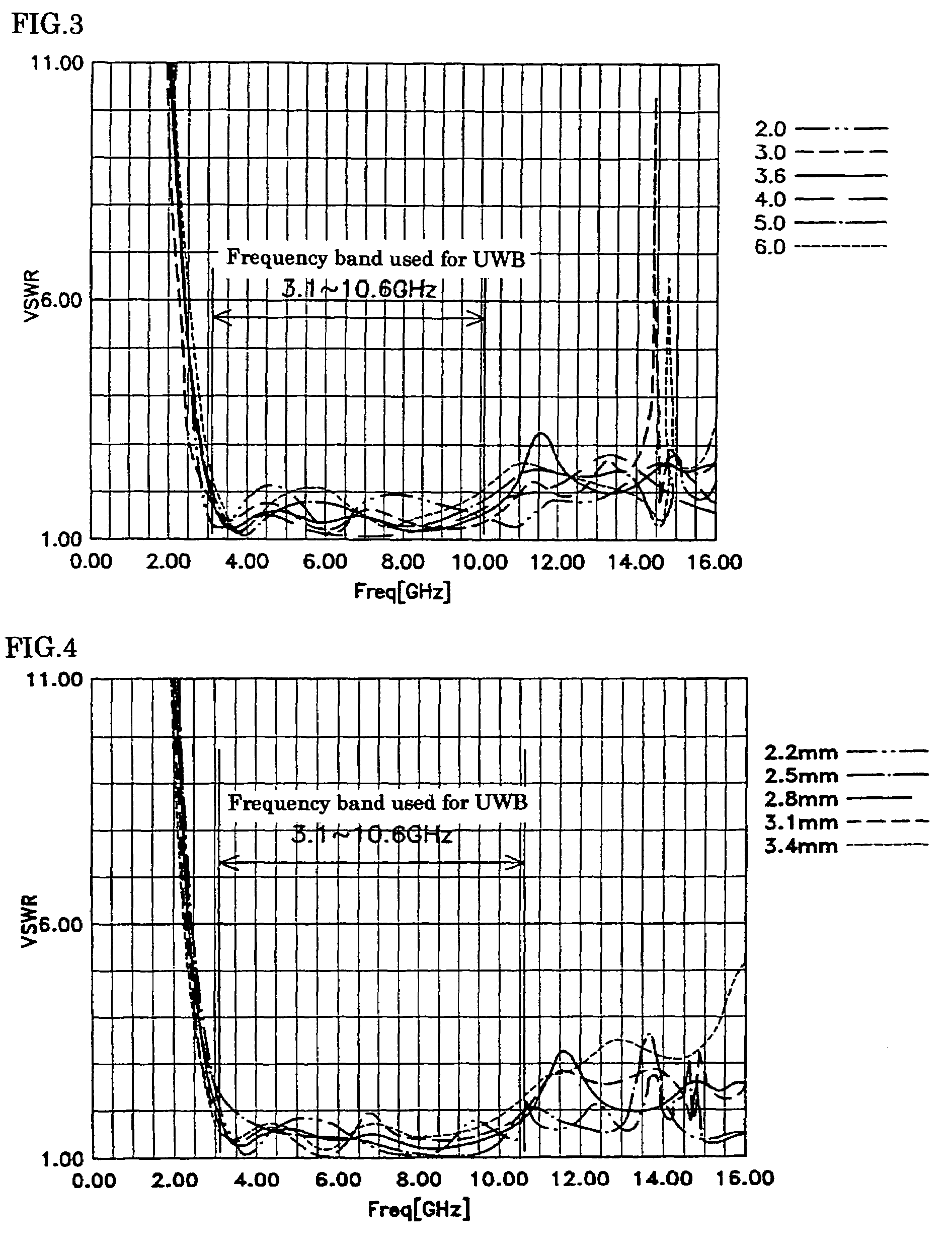
[0133]FIG. 30 is a graph showing the VSWR simulation results when varying the diameter C of the reflector 130c. From this graph, it can be seen that a band-stop filter can be configured by providing the reflector 130c. Thus, the effect is achieved that if the desired frequencies can be cut by the reflector 130c, it is not necessary anymore to provide the antenna 110c with a separate band-stop filter.


PUM


Abstract

A biconical antenna according to the present invention includes a columnar dielectric member having frustum-shaped cavities extending respectively from an upper surface and a lower surface toward a center of the columnar dielectric member, wherein flat surfaces of apex portions of the frustum-shaped cavities are parallel and in opposition to one another; a frustum-shaped feeder portion made of a conductive film provided on an inner surface of the upper cavity; and a frustum-shaped ground portion made of a conductive film provided on an inner surface of the lower cavity. The present invention realizes a more compact biconical antenna by filling the dielectric member between the feeder portion and the ground portion of the biconical antenna.

Description

[0001]This application claims priority to Patent Application No. 2004-218431 titled “BICONICAL ANTENNA” filed in Japan on Jul. 27, 2004 and Patent Application No. 2004-218229 titled “BICONICAL ANTENNA” filed in Japan on Jul. 27, 2004, the entire contents of which are hereby incorporated by reference.BACKGROUND OF THE INVENTION[0002]1. Field of the Invention[0003]The present invention relates to non-directional antennas used for broadband communication.[0004]2. Description of the Related Art[0005]In recent years, UWB (ultra wideband) communication, which is a communication technology that uses an extremely wide frequency band, that can coexist with existing wireless technology and that allows high-speed broadband wireless communication, has garnered considerable attention. UWB communication uses a frequency band of 3.1 GHz to 10.6 GHz for short pulses of only about 1 ns duration. It enables high-speed communication by exclusively using an extremely wide frequency band of several GHz ...

Claims


Application Information

Patent Timeline
Patent Type & Authority Patents(United States)
IPC IPC(8): H01Q13/00
CPCH01Q9/28
Inventor IDA, SHOGOMUTO, DAISUKE
Owner GIT JAPAN
Why Eureka
Try Eureka