System and method for distributing photons when rendering an image using photon mapping

a technology of photon mapping and image, applied in the field of computer graphics, can solve the problems of difficult determination, time-consuming trial-and-error process, and historically impractical implementation of this lighting technique in commercial rendering products, and achieve the effect of improving image quality and overall processing tim

Active Publication Date: 2007-05-22
AUTODESK INC
View PDF13 Cites 44 Cited by
  • Summary
  • Abstract
  • Description
  • Claims
  • Application Information

AI Technical Summary

Benefits of technology

[0011]The disclosed method systematically distributes more photons to higher-energy light sources in the scene. Such a distribution is advantageous because, as a general matter, the effects of indirect lighting from a higher-energy light source on image quality far outweigh the effects of indirect lighting from a lower-energy light source. By distributing proportionally more photons to higher-energy light sources within the scene, more processing time is spent on the indirect lighting effects from the higher-energy light sources, thereby substantially improving image quality against overall processing time.

Problems solved by technology

The computational intensity of global illumination rendering has made implementing this lighting technique in commercial rendering products historically impractical.
A significant drawback of commercial renderers that implement photon mapping is that the graphics artist designing a scene usually has to designate the number of photons to be emitted from each of the different light sources in the scene during the photon mapping step.
This approach causes several problems.
Making such determinations is quite difficult given the technical complexity of most rendering applications and may oftentimes lead to a time consuming trial-and-error process.
But, as also described above, increasing the total number of photons for photon mapping may dramatically increase overall computation time (as well as adversely affect system memory requirements).
These problems are exacerbated when light sources are added or removed from the scene or when the energy level of one or more light sources in the scene changes over time.

Method used


Image

  • System and method for distributing photons when rendering an image using photon mapping
  • System and method for distributing photons when rendering an image using photon mapping
  • System and method for distributing photons when rendering an image using photon mapping

Examples


Embodiment Construction

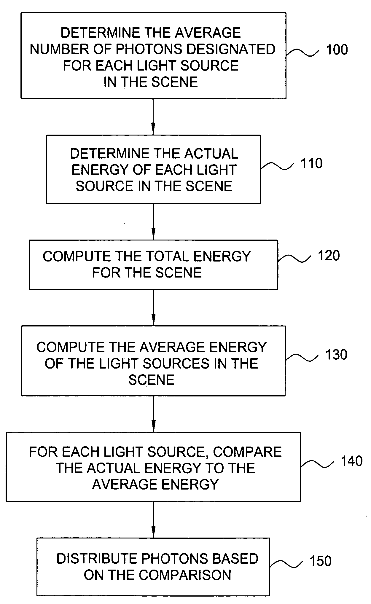
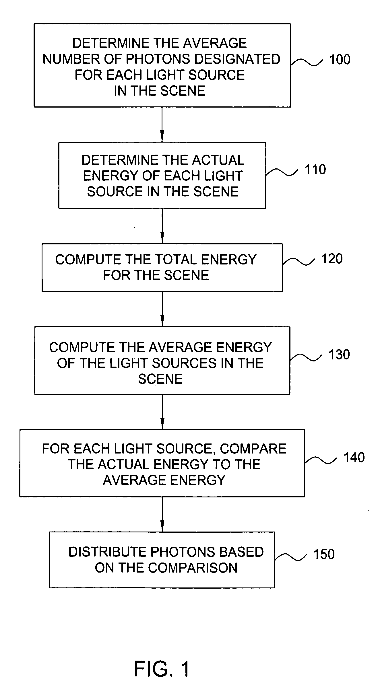
[0014]FIG. 1 is a flow chart of method steps for distributing photons among light sources when rendering an image of a scene using photon mapping, according to one embodiment of the invention. Persons skilled in the art will understand that any system configured to perform the method steps, in any order, is within the scope of the invention.

[0015]As shown in FIG. 1, the method for distributing photons starts in step 100 where a renderer controller (or equivalent functional element) in a rendering application determines the average number of photons to be emitted from each of the light sources in the scene during photon mapping. Typically, the average number of photons per light source is a value designated by a user of the rendering application. For example, the average number of photons may be a number the user inputs directly into the rendering application when rendering an image of the scene. If the user does not supply an average number of photons per light source, a default val...


PUM


Abstract

A method for distributing photons among light sources when rendering an image of a scene using photon mapping includes the steps of computing a total energy for the scene, where the scene includes a plurality of light sources, and computing an average energy of the light sources. The method also includes the steps of comparing, for each of the light sources, the actual energy of the light source to an average energy of the light source and distributing photons to each of the light sources based on the comparison.

Description

BACKGROUND OF THE INVENTION[0001]1. Field of the Invention[0002]This invention generally relates to computer graphics and more specifically to a system and method for distributing photons when rendering an image using photon mapping.[0003]2. Description of the Background Art[0004]Global illumination is a lighting technique in computer graphics that attempts to compute all light interactions within a scene to obtain a photorealistic image. Global illumination mimics the subtleties of natural light by tracing the light rays bouncing between a collection of radiating objects in the scene and incorporating the diffuse color properties of those objects in the reflected light rays. Accounting for these inter-reflected light rays when rendering an image of the scene produces a much more realistic image since, among other things, the light scattered and diffused throughout the environment creates more accurate tones and shadows.[0005]The computational intensity of global illumination render...

Claims


Application Information

Patent Timeline
Patent Type & Authority Patents(United States)
IPC IPC(8): G06T15/00G06T15/50
CPCG06T15/506
Inventor LEVESQUE, DANIELBRETON, PIERRE FELIXROBILLARD, CLAUDE
Owner AUTODESK INC
Why Eureka
Try Eureka