
Image encoding method and apparatus, image decoding method and apparatus, image processing apparatus, image formation apparatus, and computer-executable programs

Inactive Publication Date: 2007-05-22
RICOH KK
View PDF17 Cites 43 Cited by
  • Summary
  • Abstract
  • Description
  • Claims
  • Application Information

AI Technical Summary

Benefits of technology

[0013]It is an object of this invention to provide an image encoding method and apparatus capable of performing highly efficient encoding on data for a dithered image whose dither threshold values are unknown or vary, and to provide an image decoding method and apparatus for reconstructing dithered image data from the encoded data.
[0015]However, in order to make the effective type of error diffusion matrix free from restriction so as to be capable of effectively encoding error-diffused image data in which the error diffusion matrix is unknown or changes in various ways, it is necessary to hold encoded data and the sorting rules, which results in increase in the amount of encoded data and complexity of data management.
[0016]Another object of this invention is to provide an image encoding method and apparatus capable of performing highly efficient encoding on error-diffused image data whose error diffusion matrix (error diffusion factors) is unknown or varies, and to provide an image decoding method and apparatus for reconstructing error-diffused image data from the encoded data without incurring increase in encoded data amounts and complexity of data management.
[0020]A still another object of this invention is to provide an image creation apparatus capable of performing image simplification such as low resolution and removal of a detailed structure on a dithered image in which threshold values of a dither matrix are not known, that is, capable of obtaining a simplified image with a certain degree of quality without using dither threshold values.

Problems solved by technology

Therefore, this technology has a problem in encoding of the error-diffused image when error diffusion factors are unknown or error diffusion factors vary within the image.
Therefore, an effect of improving a compression rate due to dot concentration do not come up to expectations.
This means that restriction of the type of selectable sorting rules results in limitation of effective types of error diffusion matrix.
However, in order to make the effective type of error diffusion matrix free from restriction so as to be capable of effectively encoding error-diffused image data in which the error diffusion matrix is unknown or changes in various ways, it is necessary to hold encoded data and the sorting rules, which results in increase in the amount of encoded data and complexity of data management.

Method used


Image

  • Image encoding method and apparatus, image decoding method and apparatus, image processing apparatus, image formation apparatus, and computer-executable programs
  • Image encoding method and apparatus, image decoding method and apparatus, image processing apparatus, image formation apparatus, and computer-executable programs
  • Image encoding method and apparatus, image decoding method and apparatus, image processing apparatus, image formation apparatus, and computer-executable programs

Examples


first example

[0368]In the first example, as shown in FIG. 69, when the image area A0 of a photograph and the image area A1 of text exist on one page, attention is focused on the point that the size (dither size) of a dither matrix applied to an image in the photograph-image area A0 is different from that of a dither matrix applied to the text-image area A1. For example, the size of the dither matrix applied to the image in the photograph-image area A0 is “4 (dither size of 4×4)”, while the size of the dither matrix applied to the image in the text-image area A1 is “6 (dither size of 6×6)”. The size of the dither matrix (dither size) is then detected from the image after being dithered (dithered image) to separate the photograph-image area A0 from the text-image area A1 in the dithered image.

[0369]FIG. 70 shows the configuration example of an image processing apparatus according to the first example. The image processing apparatus of this first example comprises the dither size detection unit 401...

second example

[0382]The second example realizes image area separation on a dithered image by detecting a dither type in the dithered image when the dithered image has different dither types according to each object (e.g., text object and another object).

[0383]FIG. 74 shows the configuration example of an image processing apparatus according to the second example. The image processing apparatus shown in FIG. 74 comprises the pixel frequency detection unit 4021 that determines a predetermined dither size as one block in a dithered image where dither processing is executed with the predetermined dither size, and detects frequencies of pixel data in a plurality of blocks from the dithered image as pixel frequencies. This image processing apparatus also comprises the dither type detection unit 4022 that detects a dither type based on the pixel frequencies detected by the pixel frequency detection unit 4021, and the separation unit 4023 that performs image area separation on the dithered image based on...

third example

[0399]FIG. 79 shows a configuration example of an image processing apparatus according to the third example. In FIG. 79, the same legends are assigned to the sections corresponding to these in FIG. 74. The image processing apparatus shown in FIG. 79 comprises the pixel frequency detection unit 4021 that determines a predetermined dither size as one block in a dithered image where dithering is executed based on the predetermined dither size, and detects frequencies of pixel data in a plurality of blocks from the dithered image as pixel frequencies. This image processing apparatus also comprises the pixel-frequency distribution generation unit 4031 that generates a pixel frequency distribution from the pixel frequencies detected by the pixel frequency detection unit 4021, and the separation unit 4033 that performs image area separation on the dithered image based on the pixel frequency distribution generated by the pixel-frequency distribution generation unit 4031.

[0400]FIG. 80 shows ...


PUM


Abstract

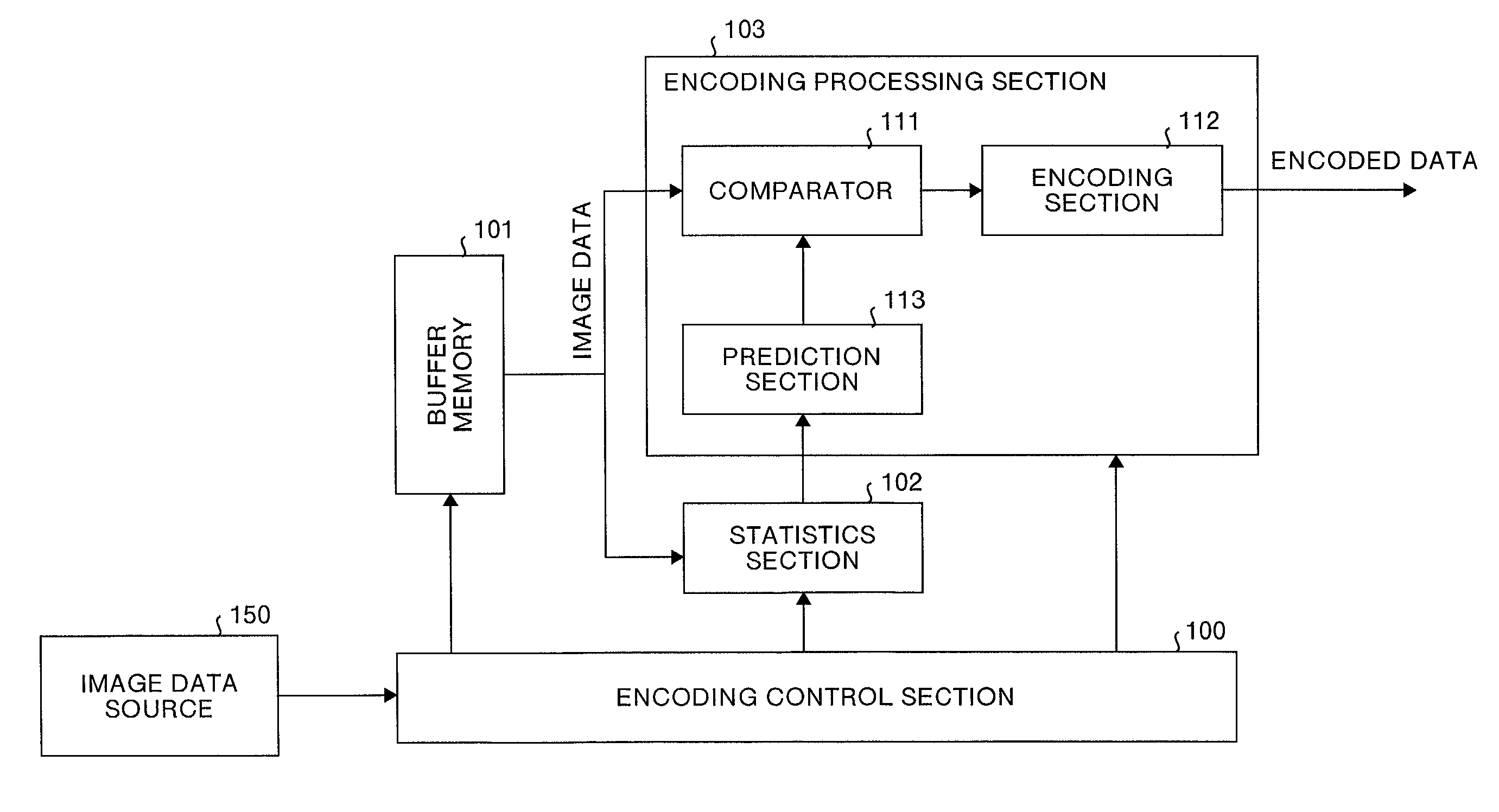
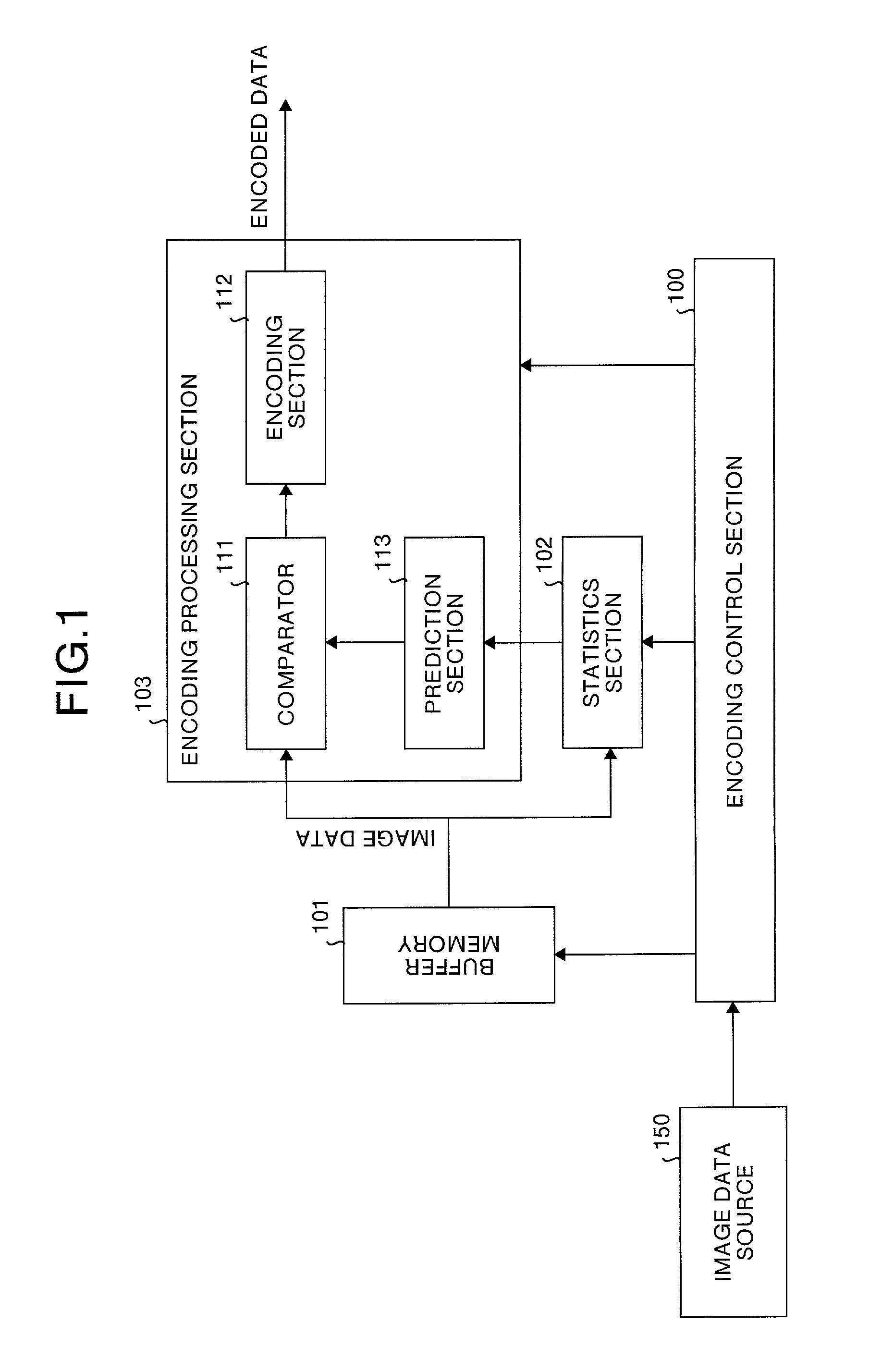
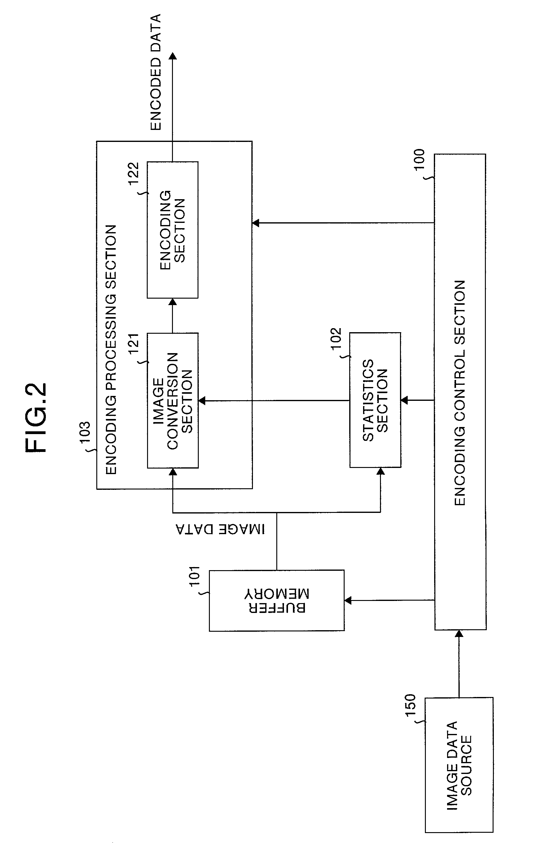
Image data is encoded using a block consisting of a plurality of pixels as a unit of processing. A statistics section extracts statistical information for each pixel value, from a plurality of encoded blocks adjacent to an encoding target block, at each corresponding position within the respective blocks. An encoding processing section performs encoding on the encoding target block using the statistical information extracted by the statistics section. The encoding processing section comprises a prediction section that predicts a value of an encoding target pixel from the selected reference pixel based on the statistical information, a comparison section that detects an error between the predicted value and the value of the encoding target pixel, and an encoding section that performs entropy encoding on the prediction error.

Description

FIELD OF THE INVENTION[0001]The present invention relates to a field of image data encoding and decoding. More particularly, this invention relates to the field of image data encoding and decoding processed through an ordered dither method or an error diffusion method that has been widely used as a pseudo halftoning technique.BACKGROUND OF THE INVENTION[0002]The ordered dither method and the error diffusion method are widely used to express halftones of photographs or the like in printers, facsimiles and the like that form an image with dots. The ordered dither method is realized by quantizing (binarizing) a pixel of multi-gradation image data based on a corresponding threshold value in a dither matrix. FIG. 86 to FIG. 88 show the ordered dither method.[0003]FIG. 86A is multi-gradation data before being dithered, FIG. 86B is a 4×4 size dither matrix, and FIG. 86C is two gradation data after being dithered.[0004]In the ordered dither method, the multi-gradation data before being dith...

Claims


Application Information

Patent Timeline
IPC IPC(8): G06K15/00H04N1/405G06T9/00H04N1/41H04N1/417
CPCG06T9/004G06T9/005H04N1/4105H04N1/417
Inventor YAGISHITA, TAKAHIROSUZUKI, HIROAKI
Owner RICOH KK
Learn More