Address resolution method for a virtual private network, and customer edge device for implementing the method

a virtual private network and address resolution technology, applied in the field of address resolution methods for virtual private networks, and customer edge devices for implementing methods, to achieve the effect of saving address resources

Active Publication Date: 2007-05-22
CIENA
View PDF14 Cites 43 Cited by
  • Summary
  • Abstract
  • Description
  • Claims
  • Application Information

AI Technical Summary

Benefits of technology

[0023]ARP is preferably used because of its availability in most IP hosts. However, it is noted that there is no mapping of each VLAN-id onto a respective, specific IP address of the local router. The ARP message is sent from a single IP address to each of the VCs denoted by the VLAN-ids. The proposed method circumvents the need to provision multiple IP addresses at the PE interface of the first CE device, and hence multiple IP subnets each intended for only two hosts. The result is an important saving in address resources.
[0024]This advantage applies particularly in the case where the VPN has a hub-and-spoke topology, with the “first CE” at the hub site and multiple spoke CEs.

Problems solved by technology

However, unlike current WAN layer 2 technologies (Frame Relay, ATM .

Method used


Image

  • Address resolution method for a virtual private network, and customer edge device for implementing the method
  • Address resolution method for a virtual private network, and customer edge device for implementing the method

Examples


Embodiment Construction

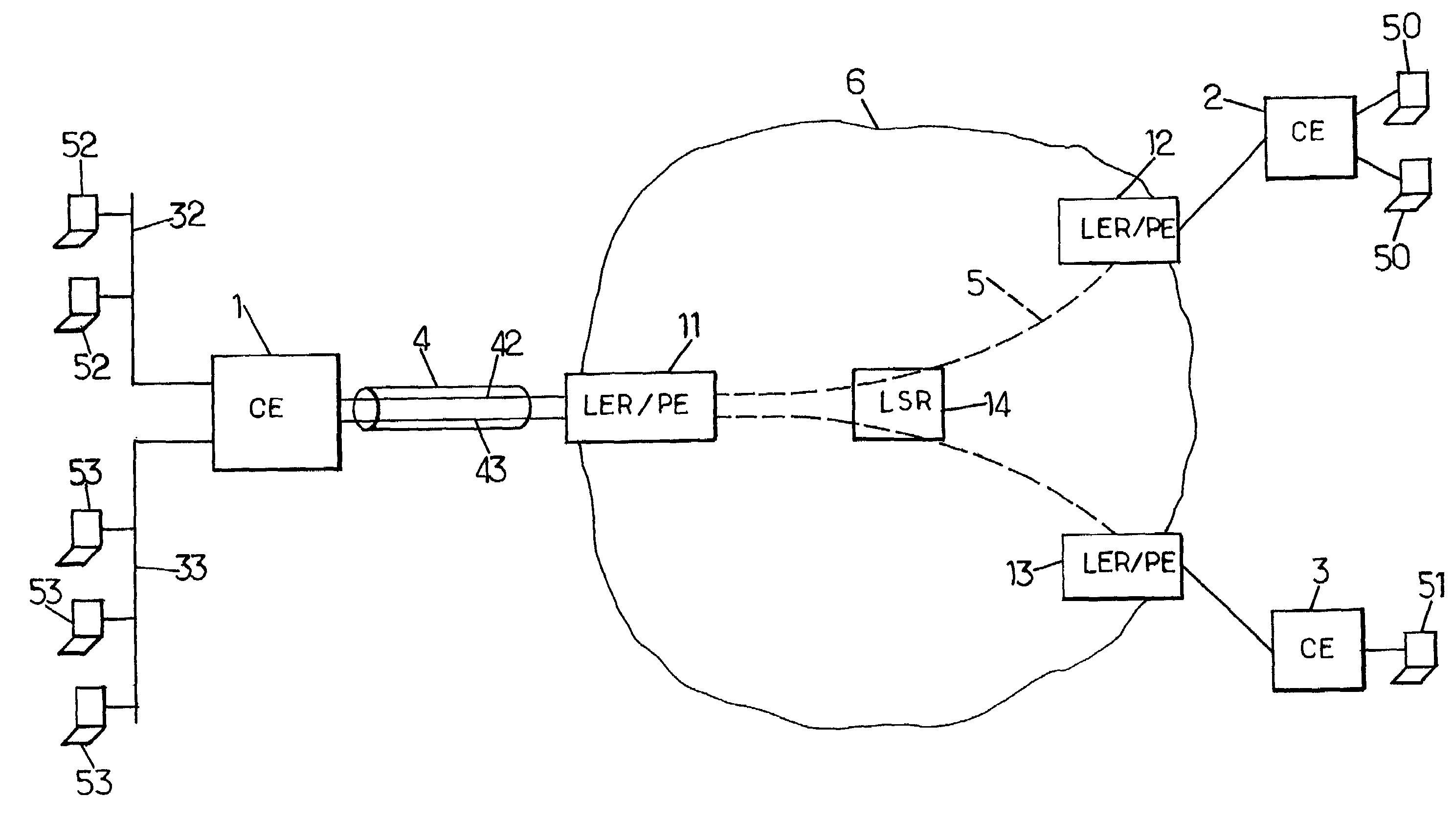
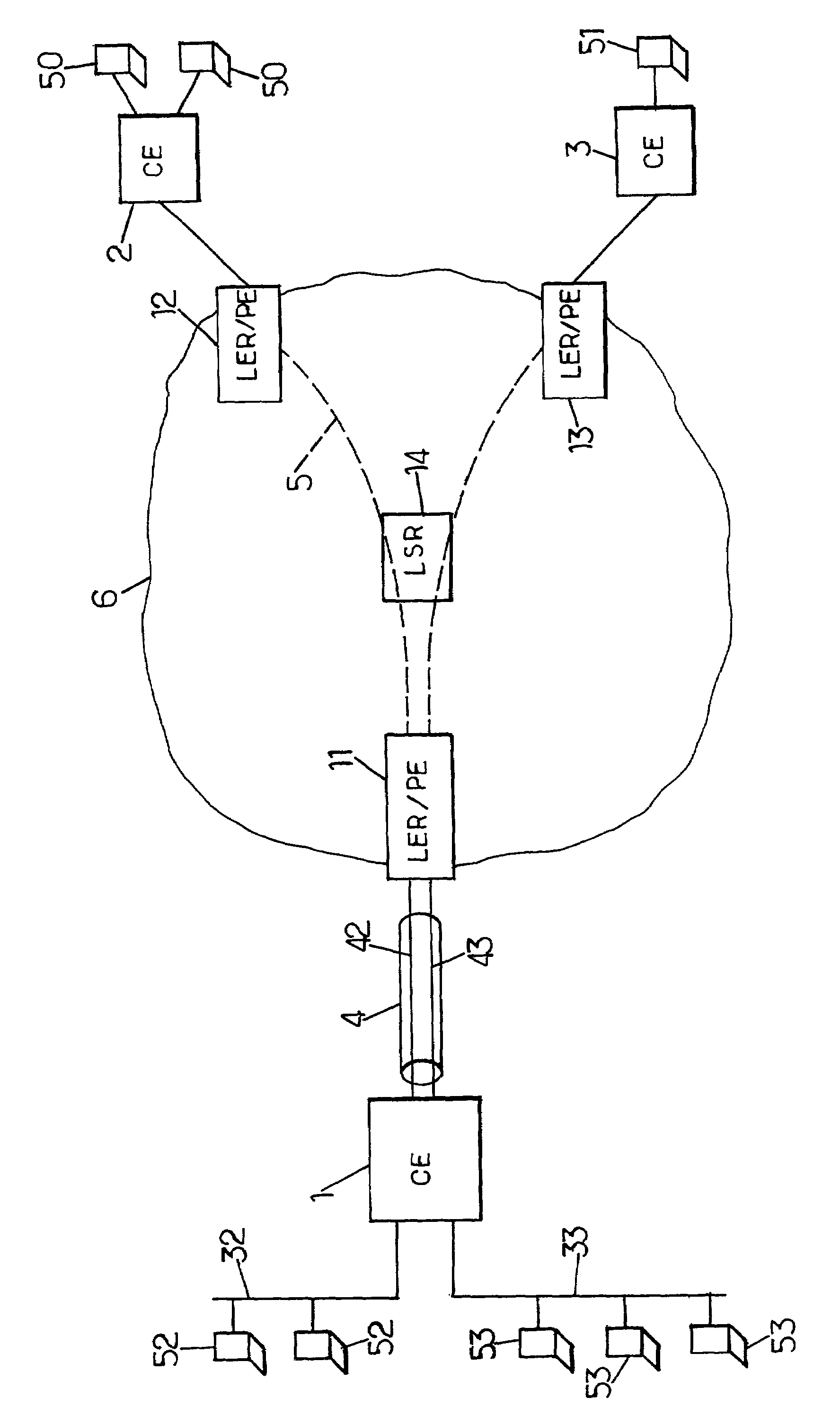
[0032]The invention is illustrated here in its currently preferred application to a VPN service of the Ethernet type using a MPLS-based carrier infrastructure. It will be appreciated that it can also be applied to other types of customer and / or provider networks.

[0033]The carrier network 6 shown in the FIGURE is for instance an IP network having routers supporting the MPLS architecture. Some of these routers 11, 12, 13 are label edge routers (LER) adapted to form PE (Provider Edge) devices for the provision of the L2 VPN service. Other routers of the carrier network 6, e.g. 14, are Label-Switched Routers (LSRs) which link the LERs by a full mesh of logical links (transport tunnels).

[0034]The FIGURE also shows CE (Customer Edge) devices 1, 2, 3. Each CE device is connected to one PE. These connections are made through an Ethernet interface carrying VID-based virtual circuits, in accordance with IEEE 802.1Q. Each CE device can be an access point to the carrier network for a set of sta...


PUM


Abstract

A virtual private network (VPN) service is provided through a shared network infrastructure, with customer edge (CE) devices each having a provider edge (PE) interface having a single layer 3 address in the VPN. An address resolution request message is transmitted by a first CE device on plural layer 2 virtual circuits of its PE interface. The address resolution request message including the layer 3 address allocated to a second CE device of the VPN. In response to reception of such request message at the second CE device, an address resolution response message is returned to the first CE device. In response to reception of this response message, the first CE device maps the layer 3 address allocated to the second CE device to a virtual LAN identifier of the layer 2 virtual circuit on which the response message is received.

Description

BACKGROUND OF THE INVENTION[0001]The present invention relates to the provision of virtual private network (VPN) services through carrier networks such as Metropolitan Area Networks (MANs) or Wide Area Networks (WANs), and more particularly to address resolution methods used in such VPN.[0002]A VPN emulates a private network over public or shared infrastructures. When the shared infrastructure is an IP network such as the Internet, the VPN can be based on an IP tunneling mechanism, as described in Request For Comments (RFC) 2764 published in February 2000 by the Internet Engineering Task Force (IETF). Another approach provides link layer connectivity for the devices affiliated to the VPN.[0003]Traditional WAN data layer 2 services provided by carriers are based on the virtual circuit concept. Data units are switched within the carrier network along pre-established trails referred to as virtual circuits. These data units are for instance packets in X.25 networks, frames in Frame Rela...

Claims


Application Information

Patent Timeline
Patent Type & Authority Patents(United States)
IPC IPC(8): H04L12/28H04L12/56H04L12/46H04L29/12
CPCH04L12/4645H04L29/12009H04L29/12018H04L61/10H04L61/00
Inventor BRYDEN, SIMONTATE, MICHAELMATTSON, GEOFFREY
Owner CIENA
Why Eureka
Try Eureka