Vortex minimizing fluid gathering and transferring apparatus
a technology of fluid gathering and transferring apparatus, applied in the direction of water cleaning, operating means/releasing devices of valves, service pipe systems, etc., can solve the problems of reducing or stopping flow, obstructed flow, and reber does not address the problem, so as to minimize the formation of vortex
- Summary
- Abstract
- Description
- Claims
- Application Information
AI Technical Summary
Benefits of technology
Problems solved by technology
Method used
Image
Examples
first preferred embodiment
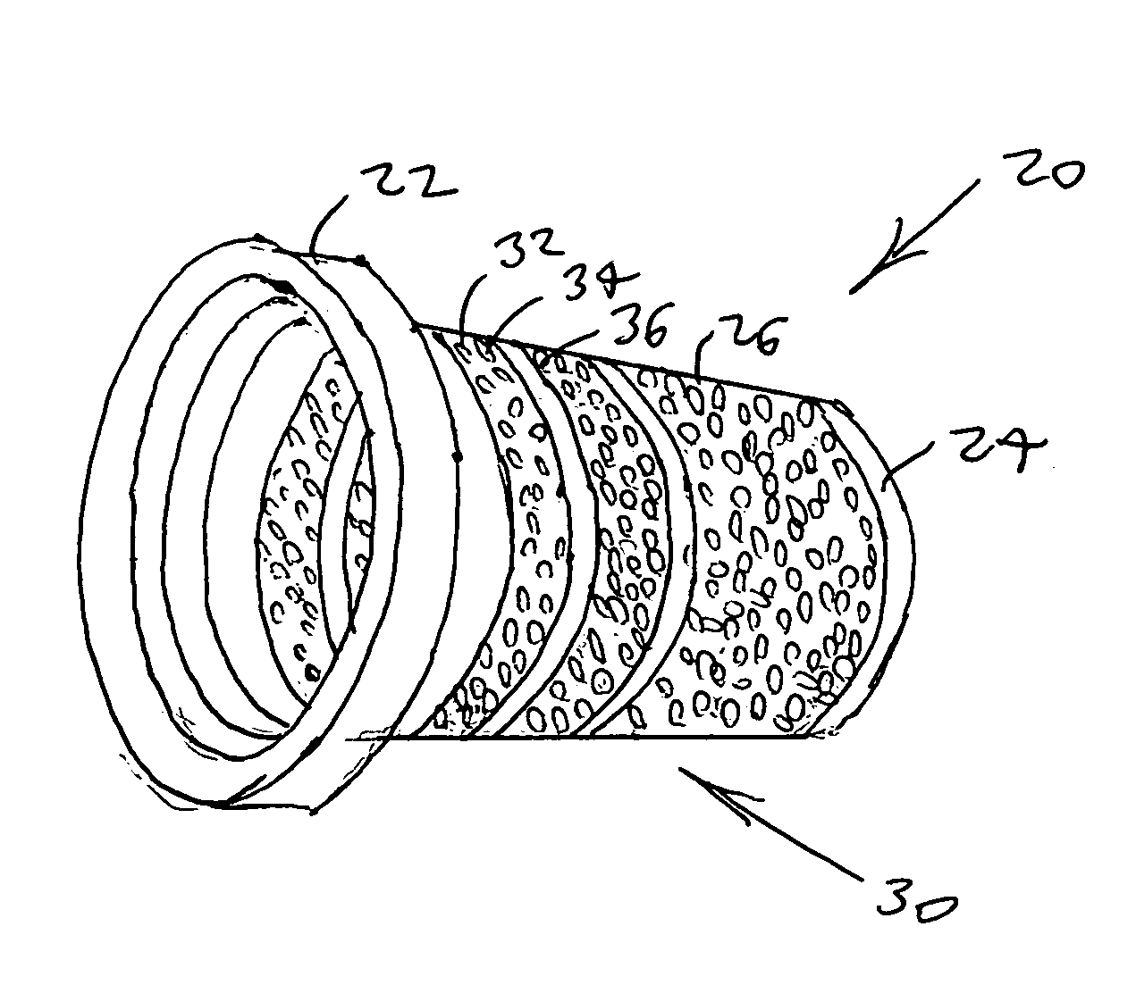
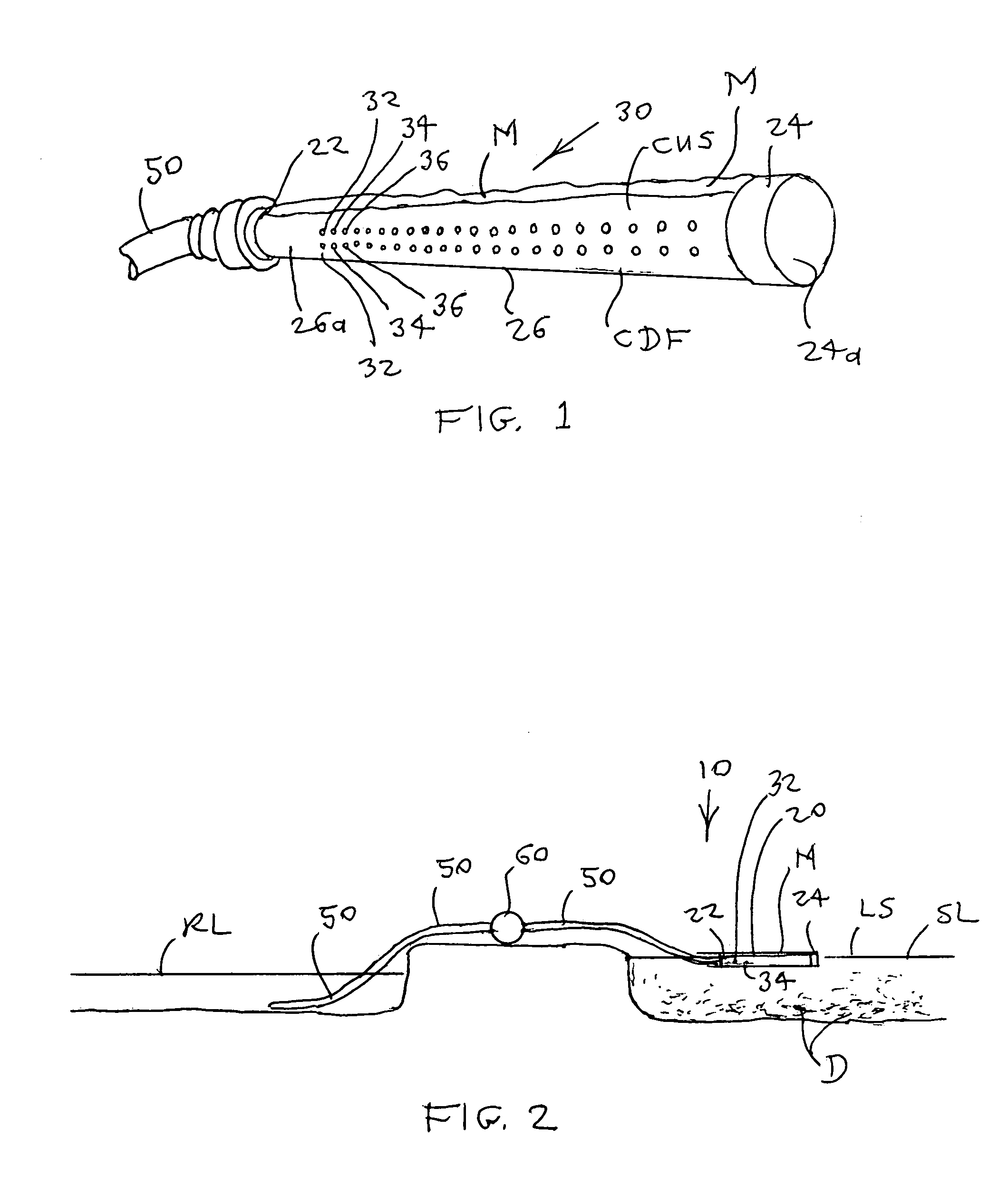
[0032]One embodiment of apparatus 10 is intended for drawing water from near the surface LS of a pond, lake, canal or quantity of flood water defining a source location SL. For this embodiment, intake chamber 20 preferably is formed of a substantially rigid material such as polyvinyl chloride (PVC) and intake ports 32-n are arrayed along the intake chamber side wall downward portion surface COF. See FIG. 2. An intake float structure 70 as above-referenced is provided. A water transmitting conduit 50, preferably in the form of a flexible hose, extends from the intake chamber discharge end 22 through a water pump 60 to a liquid receiving location RL and is discharged as needed.
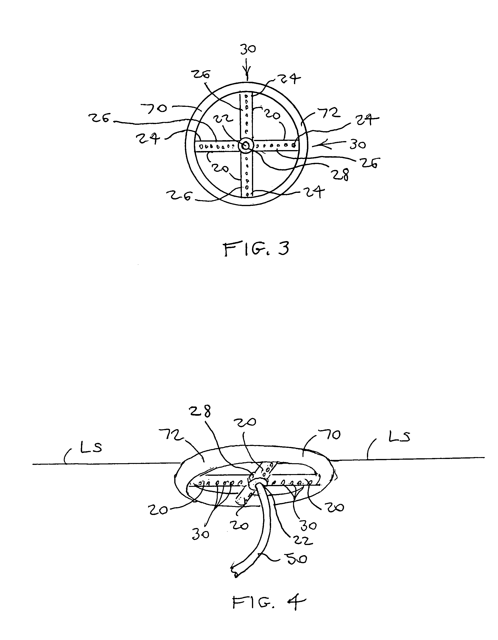
[0033]The intake float structure 70 preferably includes a buoyant barrier loop 72, within which the intake chamber 20 is mounted diametrically across the interior of the loop 72, for blocking floating debris D from reaching the intake ports 32-n. It is preferred for this embodiment that intake chamber 20 include...
second preferred embodiment
[0034]A second embodiment of the apparatus 10 is for gathering or “skimming” spilled oil forming an oil layer L floating on the surface LS of a source location body of water SL, which also functions as a boom to contain the oil layer L. Intake float structure 70 includes at least one float tube 82 having a tube closed end 84. The series of intake ports 32-n are arrayed along the chamber side wall 26 at the chamber upward surface CUS for drawing oil from layer L downwardly into the chamber 20. The float tube 82 is secured laterally adjacent to the intake chamber side wall 26 with linking lines 86 beside and parallel to an array of intake ports 32-n so as not to obstruct the intake ports. Sealant S preferably closes any gap between float tube 82 and chamber side wall 26, so that tube 82 protrudes above the water surface LS and acts as a boom. Buoyant material M is preferably added to chamber upward surface CUS and together within float tube 82 orients the intake ports 32-n upwardly, s...
third preferred embodiment
[0035]A third embodiment of apparatus 10 is incorporated into and may be treated as including a dam 100 in a stream of water trapping debris D on the water upstream side 110 constituting the source location SL, the apparatus 10 passing only substantially debris-free water to the water downstream side 120 constituting the liquid receiving location RL. See FIG. 5. Once again the combined intake chamber 20 and intake float structure 70 are deployed within the water upstream side 110 source location SL. The transmitting conduit 50 preferably includes a dam pipe 52 passing through the dam 100 from the water upstream side 110 to the water downstream side 120 and opening into downstream side 120 below the level of intake ports 32-n, and a flexible hose segment 54 extending from the intake chamber discharge end 24 to the dam pipe 52 so that gravity drives water through the intake chamber 20, through the transmitting conduit 50 and thus through dam 100, to the water downstream side 120. The ...
PUM
 Abstract
Description
Claims
Application Information
 - R&D
- Intellectual Property
- Life Sciences
- Materials
- Tech Scout
- Unparalleled Data Quality
- Higher Quality Content
- 60% Fewer Hallucinations
Browse by: Latest US Patents, China's latest patents, Technical Efficacy Thesaurus, Application Domain, Technology Topic, Popular Technical Reports.
© 2025 PatSnap. All rights reserved.Legal|Privacy policy|Modern Slavery Act Transparency Statement|Sitemap|About US| Contact US: help@patsnap.com


